Sunday, 9 December 2018

December 2018 meeting

On a cold day in Edinburgh, we nonetheless mustered a table-full of 2mm modellers: Alisdair, Alistair, Andy, Jim, Stephen, Chris, Phil, and Roy from the Grampian group met at Graham's house.

After the customary tea, coffee, chat, soup, bacon rolls, and mince pies (thanks Roy), we proceeded to this month's demonstration. This was by Alisdair, who showed us how to (irreversibly!) modify commercial N gauge metal-tyred wagon wheels for use on 2mm finescale track. His chosen weapon was his 1970s-vintage Unimat lathe, still going strong and useful for all kinds of small modelling jobs.


The 2mm finescale standards are given in the Association Yearbook and online. For convenience the relevant tables are reproduced here.


The main dimension of interest is FW, the flange width. These tend to be around 0.5mm in modern N wheelsets, and although this is an improvement on the 0.7mm common on older wagons, it is still too wide to reliably go through the 2mm pointwork wing-rail flangeway (WF) and check-rail flangeway (CF) at 0.48mm and 0.53mm respectively. The 2mm standard for FW is 0.3mm. Cosmetically, it is also worthwhile reducing the tread width (TR) to 1.0mm, so that the wheel profile looks more prototypical.

Alisdair explained he'd first tried modifying wheelsets when he first moved to 2mm scale from 4mm. He found an article in "Model Railways" which recommended using collets to hold wheels. It seemed to make sense, so he turned his own collets in the Unimat from brass and sawed slits so they could be compressed gently in a three-jaw chuck to hold the wheelset by the tyre of one wheel, without removing the wheels from the axle.


The first one didn't work, because he had not tapered the inner diameter to suit the wheel tyre coning. The second one, with taper, worked once then also lost grip. Frustrated, Alisdair put the collets to one side and resigned himself to buying new wheelsets from the 2mmSA shop or sending N wheelsets off to the Association's wheel turning service. Which as we all know is very efficient and remarkably good value. But there was still a nagging wish for the satisfaction of doing the job himself.

A chance conversation with 2mmSA magazine editor (and former FCAG regular) Anthony Yeates suggested a new direction: simply hold the wheelset lightly in the three-jaw chuck , and support the other end at the axle pinpoint in a length of brass tube in the tailstock chuck. The tube acts as a "hollow dead centre", holding the axle concentric and providing enough support for a tool to be used to turn down the wheel flange and face. Here's the tube in position in the tailstock chuck.


To cut the metal, a boring tool was used, since it was small enough to fit between the two wheelsets on the axle. The aim is to do the work without removing the wheels from the axle, which risks destroying their concentricity. After setting and trueing the wheelset in the chuck with the axle in the tailstock support, the first operation is to thin the flange of the wheel in the 3-jaw chuck, then without disturbing the workpiece, thin the tyre of the other wheel. The chuck is then slackened off, the workpiece reversed and trued again, and the second flange and tyre are dealt with.

Here's the operation in detail. First the wheelset is gripped in the three-jaw chuck, which is tightened to hold the wheel lightly.


The support tube is placed in the tailstock chuck which is tightened firmly and rotated to check for concentricity. The tailstock is then advanced to the axle end:

and its spindle advanced so the tube is positioned on the axle pinpoint so there is no slack, but without undue pressure.
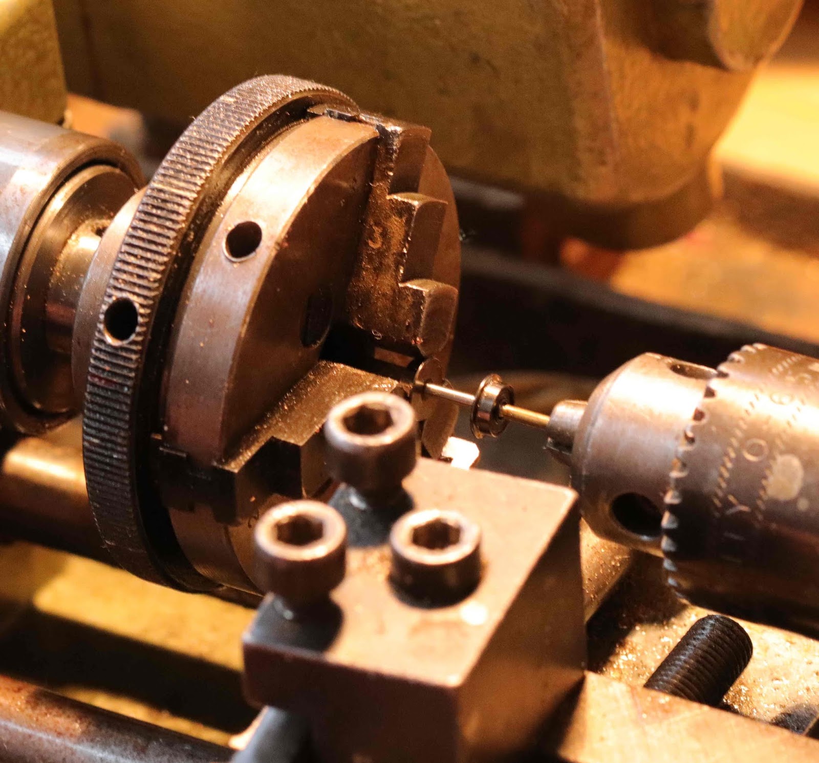
The chuck is spun once or twice by hand to check the whole thing is concentric, then tightened firmly using its tommy bars. It's important not to overtighten the chuck, or the wheel tyre will be dimpled and ruined. Don't forget to remove the tommy bars from the chuck!

Here's the setup viewed from behind - headstock and 3-jaw chuck now on the right, tailstock on the left. We're going to remove metal from the green-line side of the flange first until dimension FW is 0.3mm, then from the green-line side of the tread until dimension TW is 1.3mm.

The flange width is measured with a vernier gauge to determine its current width, 0.3mm is subtracted, and that's the amount of metal which needs to be removed. At this point a graduated handwheel on the tailstock is very useful, to give a fairly reliable indication of how far to go.
With the lathe still switched off, the tool is advanced until the edge is just touching the back of the wheel, backed off slightly,
then eye protection is worn and power is switched on (Alisdair use a fairly high cutting speed for brass, about twice that recommended for steel, with spit as lubrication)
and the flange is thinned with a multitude of light cuts, each time feeding the tool from the flange edge towards the axle, backing out, then advancing the tailstock slightly with its handwheel and taking the next cut.

Once the dimension judged by the handwheel gradation is close, the lathe is stopped and the flange dimension checked with the vernier gauge.
then the flange is brought to size with a final light cut or two.

Next the tread width of the other wheel on the axle is reduced, with the same technique. Care is required since the wheel may move on the axle if too heavy a cut is taken

The lathe is stopped, and the wheelset reversed in the three-jaw chuck, and with the lathe under power, the squared-off edge of the first reduced flange is given a light touch from an nail file emery board (from a chemist or pound shop, or swiped from a dressing table) to round it off, to avoid it catching on point blades, risking derailment. (The photo shows the principle, but in practice the tailstock support would be engaged).
Then the same set of operations is carried out again, to reduce the second flange and second tread and round off the second flange back. 

The comparison shows the difference in appearance between unmodified and reduced wheelsets.
The wheels are now set to gauge and are ready for use in a wagon or coach. Disc locomotive wheels can be dealt with in the same manner, but spoked wheels generally can only have the flange reduced since the spokes will distort or shatter due to lack of support if an attempt is made to reduce the tread width.

Alisdair also showed us his latest wheel manufacture efforts, having rejected those he showed us last month.


The tyre is turned from steel. The brass insert is made by turning a disc and half axle as one piece, ensuring that the disc is a snug fit in the tyre. Spoke position are marked out using the lathe (switched off) as a dividing engine: the insert is held by its half axle in a chuck in the headstock, a tool is placed in the toolholder which is advanced to scratch a reference mark on the edge of the disk, the tool is backed off, then the headstock rotated by hand the correct number of degrees, and the position of the next spoke scratched on by advancing the tool. If there are no angular positions marked on the headstock, it is easy enough to add a paper disk or marker pen dots. Once the spoke positions are marked out, the spokes are cut and filed to shape. We did not find out whether the inserts are glued or soldered in place. Maybe Alisdair has not got that far yet!

After this we had intended to do some further work on Sauchenford's fiddle yards. Alisdair was meant to have brought these with him from Glasgow, but unfortunately when he unpacked his car he found he'd left them behind. So there was nothing for it but to unpack individual projects and get on with that.

Thanks Alisdair for an informative talk which demystified another 2mm "dark art".

Saturday, 20 October 2018

October 2018 meeting

Once more in sunny Edinburgh for this month's meeting. Alistair, Alisdair, new face Alastair, Stephen, Andy, Nigel, and Simon met at Graham's house.

Alisdair gave a short talk on "wagons from plastic kits", starting with a look at the 2mmSA 1887 RCH kit and how it can be bashed into a number of interesting variants: he showed us a North British 3-plank and a Highland 5-plank wagon:


He also reminded us of the Buchanan Kits strapping etch designed for this wagon, which can be used to create the characteristic Scottish "cupboard door" mineral wagons:


The mouldings are rather thick in this kit and can be considerably improved by thinning them down with a large file, then scribing planking on the back:

More modern prototypes covered included BR 16-ton minerals: comparing the Association plastic kit with the Stephen Harris etched version, and the relative amount of time required for each:


One issue with plastic kits is the tendency for their sides to bow in (while the prototype tended to bow out after extended use). Alisdair counteracts this with a strip of Plasticard slightly wider than the wagon, inserted and left for a few weeks so the sides regain the correct shape. The Association Ministry of Works coal wagon kit was also discussed, with a warning that neither of the two etched chassis suggested for this moulding fit it well (see the instructions for 2-501c), and that careful work is required to make a convincing wagon.


While this was going on, Nigel, ever industrious, worked away at wagon wheel assembly:


Stephen had a Revolution Trains' Cargowaggon in 1:148 scale for us to admire. The printing is very fine:


After lunching on bacon rolls, we moved on to consider the business of the day. The objective was to do further work on Sauchenford's fiddle yards, cutting and fitting brass plates where required. This necessitated a fair bit of "planning": everyone had an opinion.


Our external assessor for the day, Mick Simpson from the North East Area Group, arrived in time to polish off the last bacon rolls and some cake. He showed us his party trick of making chocolate biscuits disappear:


He also dispensed much valuable advice regarding Electra couplings. He was able to watch Alisdair explaining finescale techniques to Alastair, who also works in 5-inch gauge live steam, and who'd come along for the first time to get some advice on the layout he's planning based on the original, pre-Forth-Bridge South Queensferry station. I think he'd expected 2FS to be more delicate:


Next month's meeting is likely to be in Lockerbie.

Saturday, 1 September 2018

September 2018 meeting

Alisdair, Alistair, John, Andy and Graham met at Jim's house in Biggar this month. The main business of the day was elimination of the sector plates from Sauchenford's fiddle yards, replacing them with cassette connections. Much scraping, sawing and screwing went on, no fingers were damaged, and we hope this will make the layout easier to operate in future.


Half-way through we paused for refuelling of soup, bacon rolls, tea and coffee. Then it was back to work (well, it was back to work for Alisdair, most of the time the rest of us leant on our shovels and made helpful comments). There was a small amount of show-and-tell. Alisdair has been experimenting with his Silhouette cutter, and had reduced some WCJS coach sides from the Caledonian Railway Association's pattern library (members only access - but you can become a member here) from 4mm scale to 2mm, onto 5 (I think) thou styrene sheet. He'd brought a test print with him.


It will be interesting to see how that project progresses. Andy had brought a part-completed loco chassis and Graham had some partly complete Foxhunter LNER fish wagons (does anyone know where he can find more of these kits?)

Jim had his footbridge for Dunallander, reported on last month and also in his RMWeb report, in an advanced state of construction. Comment from me is superfluous!


The ribs on the etched roof are added from styrene strip.


There was also the chance to view and admire Jim's Kirkallanmuir layout. Here are a few random images.


The point rodding and mechanism covers add realism to the trackwork.


A driver's eye view from the Down loop, waiting for the road to Bonkle. (Yes, all the signals work, including the ground signals).  It's about to pour with rain. The stationmaster is beside himself with fury, unable to find the porter whose task it is to fill, trim and light the signal lamps as dusk approaches. Someone's going to get wet ...


Kirkallanmuir Weighs signalbox.


A few detail shots of wagons: the first two were, I think, built from kits by the late Geoff Balfour; his Midland wagon was re-liveried by Jim. The Addie wagon is Jim's build of a 2mmSA 1923 RCH 7-plank kit (part 2-551 here), hand-lettered.


Then there was more tea, coffee, cake and chat ... and a casual question about Jim's version of the Alex Jackson coupling led to quite a detailed explanation of the various jigs he uses to make them. No photos I'm afraid but Jim may be cajoled into giving another tutorial session at a future meeting.

Talking of which, the next FCAG meeting will be on October 20th, in Edinburgh.