Monday 14 December 2020

December 2020 FCAG meeting

Our December meeting was once again a virtual affair, using the Association's Zoom account with the Chairman's kind permission. Since it was a truly dreich winter day, I think most of us were glad of the excuse to stay in.

Alisdair, Martin, Jim, James, Tony, Richard, Mick, Simon, Andy, Graham, Chris G. and Nigel appeared on screen for a down-to-earth Show and Tell session. Martin went first and showed a nicely-weathered rake of wagons, which had benefitted from his painting skills from wargaming figures. Unfortunately, I did not get screenshots of his work (sorry Martin) but maybe he'll give us an entire session on weathering another time. 

Martin had also recently tackled an an Easitrack turnout kit, which had gone well until he started to file the planing of the switches. This caused problems. We talked about the various methods of tackling this job, and it turned out to be an issue for many of those who'd tried the kit - more of this later. As usual, each expert had a slightly different way of tackling the job, so the discussion took some time. 

Martin raised another good question: which is the best 2mm steam outline kit to cut your teeth on? Mick pointed out that the usual advice, namely to find an 0-6-0 tender prototype, is given because this gives twelve contact points for reliable pick-up and thus maximises the chance of something running smoothly first time.

Richard had also tried an Easitrack point kit, and this time I managed to take a screenshot.

Construction was straightforward and took him a week of evenings, but like Martin, Richard found things went wrong when it came to filing and fitting the switch rails. Mick recommended sliding the stock rails through the chairs for three sleepers past the tiebar, allowing the switch rails to be slipped into place. The stock and switch rails can then be unobtrusively bonded with a small strip of brass. Another of Mick's tips was to replace the solder tag on the crossing with a longer piece of brass strip, long enough to pass through the baseboard. This allows the crossing to be removed easily if it's necessary to adjust or replace the closure rails.

Richard was brave enough to show us a cruel close-up of how, in frustration, he had attempted to get the switch tips to sit in neatly against the stock rails, after being told in a previous meeting that joggles were for Great Western modellers only and that porridge-eating, caber-tossing, loch-swimming, hair-shirted inhabitants of Ardnamurchan were not permitted such simple solutions. The alternative he came up with was to file a recess in the stock rails themselves. This caused some concerned murmuring from the experts who pointed out that although this will work well in the facing direction, it is likely to cause problems when passing through in the trailing direction as wheelsets are likely to bounce off the recess when it ends suddenly and derail.

On seeing the photo, the diagnosis was that the planing length of the switch tips is too short. According to the 2mmSA "Track" book, "A" switches should have 11mm planing and "B" switches, 15mm. Sometimes cruel photos have their uses, for diagnosis would have been difficult without it.

It turned out that not only Richard, but several others were slightly confused by the book, which deals with filing of crossing vees and switches in the same section, bouncing around somewhat between the two. The "file-bend-file" technique of filing a taper on one side of the rail until just reaching the web, then bending the rail so that the filed taper is in a straight line with that side of the rail, and finally filing the taper on the other side of the rail, is intended to be used for switch blades as well as crossing rails. Several people mentioned that when filing the second side, it's only necessary to file away the upper head of bullhead rail, leaving the foot substantially complete so that the switch has a little more strength. The wheel flange only runs along the upper head after all. 

The experts also mentioned that, although joggles are not their cup of tea, most of them put a slight "set" in the stock rail - a single kink really, rather than the double-kink of the joggle - but only enough to take the rail a few degrees away from straight. This allows the switch rail to sit in more neatly. Easier to do with soldered track than in the Easitrack kit, however. (And ... tell it not in Gath, whisper it not in the streets of Ascalon ... even the Caley used joggles when they had to - such as in a true three-way point. See here).

Further anent track, Andy showed us his tiebar design, which he wrote up in the magazine a few years ago.


James shows us a small test track and power supply unit he completed recently, as well as a DCC track voltage tester he's currently working on. I missed photos of these too - sorry James! - but again, it would be interesting to have more details in a future meeting.

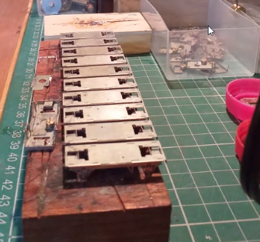
Simon has been batch-building LNER fish wagon chassis. His working practice is based round plastic ice-cream tubs ... it is necessary to spend several evenings eating ice-cream before starting. After that, they are used to keep the different stages of production neatly segregated, so a batch of chassis can be worked on a few operations at a time, slowly (or quickly, in Simon's case) bringing the whole lot to completion.


Other work has included a 2mmSA LNER Toad kit and a mystery-origin kit for a vaguely Southern brakevan picked up out of curiosity at Perth show some years back. No doubt someone knowledgeable (Chris Gough perhaps, our local Southern aficionado!) can tell us what the exact prototype was. Are these things on the end platforms sandboxes?

Finally, Simon showed us the timbers for the tandem he is working on for the group layout. He's a set man, not a joggle man, before you ask.

Tony has also been batch-building, and showed us a box full off Black 5 tender inner frames and cabs. Yes, there are nine cabs in the box, all mostly complete.

Jim showed us the latest progress on Kirkallanmuir's station building, which has gestated from its unfinished state shown here:

to a detailed model with window, door and lettering detail added from his own etches. His RMWeb write-up, as usual, gives full details.

The building shell is from 0.040" styrene with 0.020" window sills and 0.010" overlays for quoin details etc. The method of cutting the 40-thou' material is to press heavily an a steel rule and make many light-pressure cuts with a sharp scalpel blade: typically 5 or 6 for 0.020" and more for the thicker material (or score and snap). Jim eschews safety rulers but others spoke highly of them. Alisdair mentioned that cheap Chinese-import rules are in fact better for the job because the poorly-finished edge has the effect of gripping the styrene more firmly that a higher-quailty but smoother-edged rule.

Chris took us though his the latest stages of his LMS 4F build (2mmSA chassis with a Mike Raithby body etch).


Issues he had to solve included the drawbar design, the motor mount, and the gearbox: the chassis etch has a fold-up gearbox but the tabs and slots had not etched well and did not locate properly. Ultimately, and with advice from some more experienced members at a previous physical meeting, it was easier to remove the etched gearbox and fabricate one from brass. The splasher tops in the body kit were another source of issues: Chris learned the hard way that the tops are designed to go above the sides rather than between them - only then is there enough clearance for the wheel flanges.

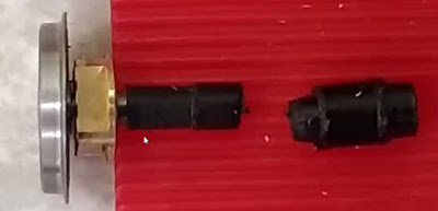
Nigel showed us progress with finescaling the N Gauge Society Hunslet industrial diesel. On taking to bits an early prototype example, he discovered there is very minimal clearance between a spur gear in the model's drive train and a standard (1.5mm) 2mmSA driving axle centred by its drop-in replacement bearing:

His proposed solution is a special axle muff which shaves 0.2mm off part of its length to clear the spur gear. If that does not prove practical after checking for tolerances on more recent production models, a plan B exists using a thinned axle.

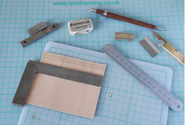
Mick had an intriguing set of illustrations of how to make card wagon bodies from standard file dividers. The prototypes are from local industrial railways. First the sides are drawn on the card:

 The plank lines are scored before the sides are cut out.

The model is assembled square:
End stanchions and hopper sides are added:

Here a 2mmSA chassis has been used to complete the model.

The final shot is of a similar North Eastern pre-grouping hopper in card, a model he completed in 1984,

Alisdair brought us up to date with progress on his Highland Railway "Yankee Tank" 4-4-0T. The chassis has advanced to a state where it is square and flat, and everything runs smoothly. The frames are from 0.55mm brass, which he found much more pleasant to use than the thinner material often recommended. They are also blackened with a Carr's proprietary liquid, rather than painted, which will hopefully overcome problems with unsightly chips as the model is handled. 

The brake rigging (brass shoes, nickel-silver hangers, PCB cross-shafts, and a wire pull-rod) locateinto a thin tube which receives the pull-rod, visible below.

Stay-alive capacitors are shoehorned into a space below the footplate. A lump of lead keeps the bogie from floating off the track.
The boiler was rolled round turned bands, soldered, then cut away for the motor, as seen below.

The tank and cab sides were cut from sheet with a piercing saw.

Boiler fittings have been turned on a lathe with needle files.

That pretty much completed the showing and telling. The next virtual meeting is likely to be on 9 January 2021, with a tentative theme of "travelling toolkits".

Whether you are of the Set or Joggle persuasion, the Forth and Clyde Area Group wishes all 2mm modellers, in Scotland and beyond, a Merry Christmas and a guid New Year tae yin and 'a.

Sunday 15 November 2020

November 2020 FCAG meeting

November's Zoom get-together had the theme of "Tools – Those I have Loved and Hated". This worked quite well, with each of the twelve attendees (Chris M, Chris G, Alisdair, Alastair, Mick, Nigel, Andy, Richard, James, Stephen, Simon and Graham) given ten minutes maximum to say their piece. Interestingly, several themes kept recurring, at least regarding the most useful implements. (There was a certain amount of off-scene chortling from assorted eavesdropping WaGs - they know who they are - as the T-word was bandied about thoughtlessly by our earnest group members. We must find our entertainment where we can in these days of social distancing!)

I wasn't nimble enough to screen-grab everything that was shown, so please forgive the limited choice of images. Does anyone else have problems with the Alt-Shift-T key binding for Zoom under Linux Mint 18.2, or is it just me?

Simon's favourite was a pair of simple but sturdy metalworking dividers - made by Starrett, and sourced secondhand by a helpful workmate - which he finds ideal for scribing planking and the like in styrene sheet.

His pet hate was scalpels, on account of the lacerations suffered from a young age from their use. He still has all his fingers however.

Mick showed us his Cowells 90 ME lathe, and described his latest project with it - a servo-operated "arrester" which stops wagons moving by sticking a rod up to engage them from underneath. This is something to do with a scheme to reproduce the Bowes rope-worked incline in 2mm. We probed for further details but mostly got mysterious smiles in response. No doubt all will be revealed in time ... His least helpful gadget is a clamp intended to ensure that pieces of styrene are assembled at a true 90° angle:

It fails to do this satisfactorily due to the foam rubber inserts. Others agreed and the consensus was that a small steel block with button magnets is a better way to do the job.

Nigel also favoured a Cowells lathe, and showed off large amounts of tooling to go with it. A hobby in itself ... other favourites include a Mitutoyo digital vernier gauge (whose button cells last for many months, unlike cheaper models from Aldi - an observation which met with much nodding from other participants), an Archimedean drill, and a small pin vice. Although such drills are easily and cheaply found from suppliers such as Squires, Nigel made the point that they very often do not run true, and the best way to find a good 'un is to inspect a selection at an exhibition and pick the best of the bunch. 

A final favourite was a pair of toolmaker's vices rescued from a skip apparently. (Why are there no such skips where I live? All they contain is builder's rubble and soggy plasterboard. I think Nigel spins yarns like these just to wind us up!)


His least useful item was a clumsy gas torch, bought in the expectation it would prove its worth for bigger jobs, but relegated to the back of the cupboard in favour of a smaller model. (The photo is of the clumsy one; he showed the other, better torch in last month's blog).

Chris M's top picks were a hand vice of the type seen below, available from Squires for thirteen quid; and a chisel blade in an X-Acto handle for separating etch parts neatly from a fret. The blade can be re-sharpened for this non-critical application.


His pet hate was his Dremel drill stand, which contrives to hold drills off-vertical .... not quite what its designer presumably intended. Apparently this is a common problem with these stands which cannot be easily solved. Caveat emptor. Others recommended the Proxxon drill stand as the best design of a generally poor bunch.

Stephen spoke highly of plain old tin-snips for cutting sheet metal. Most people find these curl up anything they touch into a useless spiral, but Stephen explained that, with care, they will do the job very well. He uses a score-and-snap technique with a hefty scrawker to bring the workpiece close to the desired dimensions, then finishes the last couple of millimetres to size with the tin-snips. The small waste strip will certainly curl up, but the workpiece itself will stay flat.

His most-disliked choice was a resistance soldering unit. Early in his 2mm days he acquired the well-regarded London Road Models unit, but found it did not suit him, and that synchonising the foot-switch action while positioning the parts did not "click". This led to a group discussion. A stout defence was mounted by the two ex-chairmen in the group, but the conclusion was that RSUs definitely require a particular technique which does not suit everyone.

Chris G. brought us back to the theme of digital vernier gauges which eat button cells ... another dislike was his Silhouette cutter, with which he has a love-hate relationship. The "hate" part stems from his difficulty in using it to consistently cut styrene thicknesses above 10 thou, although he readily admitted that others have been successful. He is much happier with his CNC cutter (which can also carry a laser cutting head and with the right technique, deals with plywood up to 5mm). This is the unit he told us about in the March 2020 FCAG meeting, when he showed us examples of the buildings he can produce with it.

Another favourite item is wire-strippers. The yellow/orange example below is of the self-adjusting type available on eBay or Amazon for around six quid. The other set are rather more expensive - over £30 from Squires, look for "CK automatic wire stripper" - but have the distinct advantage of being able to strip insulation from the middle of a run of wire, rather than only at the end. A huge time-saver when wiring up a large layout.

Richard's favourite was the trusty old Swann-Morton plastic craft knife handle which I suspect we all started with in our schooldays - at least, many of the audience agreed with him. He gave the thumbs-down to an airbrush which he purchased with a large paint reservoir, only to find that the cleanup was so onerous that he hated to use it. The solution was to turn it upside down, remove the reservoir, and use it like a cup airbrush. Neat.

Andy showed us an interesting compact mobile toolbench and store. Lockable caster wheels mean that it rolls easily but can be instantly made stable for work. A power strip is attached to one side on a wandering mains cable.Tools are kept in the drawers or on the sliding shelves.

At the back are stored a couple of clip-on work surfaces which are attached using shelf rails from a DIY store. The vice and minidrill clamp can be repositioned thanks to a choice of mounting holes. A magnifier lamp is mounted at the back. All told, a very nice and compact design which my photos don't really do justice to.

James' best friends are a simple six-inch steel rule and a sharp pencil; and ceramic-tipped tweezers. He is less enthusiastic about his mini-drill: the stiff lead and general clumsiness mean that is generally stays in the drawer.

Graham's top choice was a flux brush made from a cut-down paintbrush stuck in a lump of cork for stability and bench cleanliness.

Another favourite is an analogue vernier gauge, with a dial readout rather than a true vernier scale. No batteries to run down ...


His harsh words were reserved for a miniature hand drill based on a scaled-down carpenter's hand drill, but made in plastic. It is rigid enough, precisely made, and has no shake in its bearings ... but it only takes drills below about 0.7mm and is far too clumsy for these. An Archimedean drill is a far better solution.
 

Alasdair, being a 5-inch live-steam man, had some enviable larger machines to show us in his workshop. His favourites are a small milling machine and his Ender 3D filament printer. He moved his camera around so quickly, however, that I failed to get even a single shot of his workshop.

Alisdair had smaller implements in mind - his favourite is an engineer's clamp, used here to hold a coupling rod for finishing. With care the jaws can be adjusted to have a truly parallel action.

He gave the thumbs-down to the type of hand clamp which most of us will have toyed with buying at a show. They look like they will be useful, but again this is a gadget which tends to stay in the drawer.

That wrapped up the themed part of the meeting. We spent the rest of time discussing the latest iteration of the Templot plan for the New Group Layout (a loco shed scene), which Jim had kindly circulated. The turntable has disappeared, and the bottom length of track will be physically separate so that DCC and non-DCC models can appear at the same time. The space at the bottom right is intended for a control panel. For simplicity, point will be mechanically operated. The shed itself will be a three-road type disappearing into the backscene at the left.

Amazingly, this time we actually agreed on it, and kept the momentum going by agreeing who would build what - since it's a learning exercise, each point will be built several times by different individuals, with the best being selected for use on the layout (or, if none are any good, sent back to their makers with a "please explain" note). A mix of Easitrack kit and copperclad-sleeper-with-Laurie-Adams-detailing-etches designs will be used. The aim is to complete these by the start of next summer, by which time, hopefully, the pandemic will have receded.

The next FCAG meeting will be on 12 December and may (or may not) be an "on my workbench" session. Better get these favourite implements out again then ...


Monday 12 October 2020

October 2020 FCAG meeting

This month's virtual meeting was on the theme of soldering: Andy, Graham, Richard, Stephen, Martin, James, chairmanJim, Simon, Chris G and Chris M provided the audience and Jim, Nigel and Alisdair formed the "panel". The following write-up is in no way a primer or even an exhaustive description of each panel member's favoured methods, but simply a quick record of what they said on the day. Those seeking a reference are directed to Chapter 5 of the 2mmSA's "Track" book.

Jim kicked off with an explanation of his personal technique. He uses a silicon phone-repair mat for a work surface, ceramic-tipped tweezers to hold components or pieces of etch, and a small piece of plywood when a firmer work surface is needed. A small brass sheet acts as an anvil on which to separate etch parts.

Soldering, he explained, requires formation of an alloy between the surface of each metal piece being joined and the solder itself. The three indispensable elements are heat, clean metal, and effective flux. The flux dissolves oxides on the metal surface and coats it, preventing new oxides from forming so that the alloy is strong, and transferring heat quickly through the joint area.

Jim's soldering iron is an ERSA RDS80 temperature-controlled model with three presets at 180°C, 300°C and 400°C - he tends to use the 300° setting.

His preferred bit is a 2mm chisel shape - this, combined with the 80W iron power, allows him to use a "quick in and out" technique to work quickly and cleanly, dwelling on the joint long enough to ensure good solder flow and an effective joint.

He prefers 188°C solder paint to paste, cream, wire or sticks, and after years of using a cocktail stick to apply the paint to the work, has recently switched to using a plastic applicator which is less likely to shed fragments into the paint. His tin of paint has lasted years: if it dries out, a drop of water restores it. Tap water in Scotland is generally soft (slightly acidic),which does not affect the chemistry of the flux in the solder paint, but those in hard water areas should use deionised or distilled water (such as is supplied for car batteries) to ensure that the flux, generally phosphoric acid, is not neutralised by the carbonates in hard water.

In the image, a drop of paint has been placed on the holes for the bearing cups in a wagon chassis etch. The cups are placed face down on the mat and the etch manoeuvered over to locate them. They are then soldered with a  touch from the hot iron, which is cleaned first by plunging it into a small wad of brass wool such as this.

When laminating layers of etch together with solder paint, Jim finds it unnecessary to tin the surfaces first - instead he simply paints the inside of the sandwich, folds the etch over, holds the two layers in contact using the tweezers, then applies the iron and draws the tip slowly round the metal surface so the solder flows. In the shot below, a multi-layer window is being built up.

The fold tabs and etch frame are not removed until the laminations are all secured.

If solder paint is not used, however, then both sides of the sheets to be laminated should be tinned first.

If the edges of laminations are apparent and this is visually obtrusive, for example on solebars or wagon framing, a useful tip is to flood the edges with low-melting-point solder or whitemetal (that is, the stuff that melts at below 100°C, not the 145°C solder) , which fills the gaps, then the edge can be tidied up with an old file. (Solder clogs files and reduces their effectiveness, so only old or worn ones should be used for this).

Another use for LMP solder is to attach smaller fittings such as chimneys and domes to larger metal objects such as boilers; the joining surfaces are tinned first with ordinary, then with LMP solder, which makes it easier to attach the small items in spite of the larger thermal mass of the boiler which can otherwise make it hard to bring both surfaces simultaneously to the temperature required for a good joint with ordinary solder alone. The bit must be cleaned after use to avoid corrosion by the different solder; alternatively, a different bit can be reserved for LMP use only.

Nigel took up the discussion with some pictures of his equipment. His soldering station, an Antex 660 TC, allows variable tip temperature and 50W of heat, and plug-in irons. Nigel works at 275-300°C most of the time. He has two irons, one with a small chisel tip, one with a round tip, and just plugs in the best one for the job in hand.

Like Jim, he cleans the tips on brass wool. Two kinds of cored solder are visible in this photo - one has a tiny amount of silver which aids flow for some joints -  as well as Carr's 188 solder paint and Green Label flux.

A wooden work board has "fences" of stripwood fitted to stop small items sliding away from the iron. Clamps of the David Eveleigh skewer-and-clothes-peg variety are also very useful to position work.

Etches and parts are cleaned with wet-and-dry paper, emery cloth, Garryflex blocks of various grits, and (sparingly and carefully, on account of the sharp stray fibres which can irritate skin, lungs and eyes) a fibreglass pencil.

Workholding involves not only a conventional small vice with smooth jaws, but this highly desirable Eclipse toolmakers vice ... I think it's a model 180.

Cleaning up is made much easier by use of an inexpensive ultrasonic jewellery cleaner from eBay. Nigel simply uses a water bath for 10 to 20 seconds.

He still prefers steel tweezers ... flux spattering on these will rapidly corrode them so they must be carefully cleaned after use, or given a quick dip in the ultrasonic cleaner.
For some jobs it's hard to beat a resistance soldering unit (RSU) - this is a London Road Models unit - it comes with a probe lead, an earth lead, and a footswitch for operation.
Work is done on a metal sheet, or metal foil, connected to the earth lead.
The probe itself is a short length of carbon welding rod, brought to a fine point using a pencil sharpener, and clamped by a small collet to the probe lead. The tip is a consumable which is sharpened as often as required, and replaced when necessary.

A recent Scalefour Society video tutorial by David Brandreth gives an excellent introduction to RSU use.

Another handy technique in certain situations is silver soldering - especially where a strong joint is wanted which will not be loosened by further work with soft solder around 300°C. The work has to be bound firmly in place using fine wire or clamps, the joint prepared with small slices of silver solder and covered with paste or powder flux suitable for the two metals being joined, then heated to between 600°C and 800°C depending on the grade of solder, using a small gas torch. 


Neither Jim nor Nigel were keen on of solder balls, preferring simply to cut small slices of wire solder, but other FCAG members were enthusiastic ball users, especially for trackbuilding to create consistently-sized chairs.

Other tips shared included being sure to plunge the iron tip into the brass wool before and after every joint, so ensuring a clean bit, better joints and extending tip life. Tips, usually made of copper, are normally iron-plated to prevent corrosion by the flux; the plating must not be damaged and the temptation to file the bit to special shapes is best resisted, or done using a spare bit. Some members spoke highly of solder cream, "hot tape" to position components accurately, and Loctite TTC-LF or similar tip tinner/cleaner for situations where despite best efforts a bit has become dirty. Cleaning up joints is helped by a variety of tools, including old files, scalpels, triangular scrapers, sharpened jeweller's screwdrivers, and so on  - here are Alistair's:


After some further discussion in the group, we moved on to ponder, yet again, our proposed group skill-honing cameo shed layout. Much discussion focused on the desirability, or otherwise, of a turntable. A plan will be finalised before the next meeting hopefully, then work will be allocated to those willing to try their hand at various tasks.

The next meeting will be a call on 14 November with a theme of "your most-useful, and least-useful, tool". This should lead to an interesting series of sheepish admissions of impulse purchases at exhibitions and flea markets!