His first attempts were made with moulded plastic universal joints fitting 1mm rod, previously available from the 2mmSA, and still offered by N Brass Locos. These worked well enough, but the 1mm rod was visually intrusive in the loco cab.(And the N Brass units use 1.5mm rod, which is worse).
His second style aimed to make the unit less obtrusive. 'O' gauge loco handrail knobs were fitted to hollow 1mm brass tube, and a stub of wire inserted through the hole meant for the handrail. The wire stubs engage in slots cut in the motor drive shaft in the tender, and in the gearbox drive shaft in the loco. Sturdy, but still obtrusive.
Alisdair's third version was conceived after building the Bob Jones-designed 2mmSA Black 5 etched kit. This contains a fold-up etch for the drive shaft which worked very well. Attempts to produce a built-up copy of this failed however: when soldering, it was too hard to stop the unit collapsing in a random heap of metal.
The next attempt followed the advice in the 2mmSA handbook: slots in the tender and loco drive shafts, and a wire shaft formed into tight loops. Again, this worked, but Alisdair found the drive shaft length to be overly critical, and the shafts had a tendency to drop out and get lost.
Still in search of the ideal drive coupling (strong, unobtrusive, minimal assembly, not dimensionally critical) he settled on a design based on 0.008" steel wire (8 gauge guitar string, about £1.25 on eBay) and slices of brass tube (Mastertools brand, pack 09944, eight 20-cm lengths of tube between 1.1 and 1.4mm, available from traders at shows or from eBay for around £6. The tube sizes don't fit into each other, but still a nice cheap source of material).
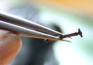
First a T is formed in the wire. (Ignore the brass collar in this shot for now).
Now the end of a piece of brass tube is slotted with a fine file (something like the 0.4mm edge-cutting gapping file, item 1-502 in Shop 1), and cut off to make a small collar.
This collar is slid over the long end of the shaft and past the kink, then fluxed, held tight against the tee, and flooded with solder. (A third hand helps). Then a second collar is slid on facing in the opposite direction, and the kink is finished into a second tee for the other end of the shaft. The second collar is soldered on in the same way. Opinions differ on whether the two tees should be in the same plane or at 90 degrees to each other. Both styles seems to work. (The photo below shows a demo piece for tee formation, with only one collar on the wire and not soldered in).
The result is a very unobtrusive drive shaft which is hardly visible when in motion. Here's one on Alisdair's Jumbo. Yes, a tender axlebox
Care is needed not to "break the back" of the loco and tender when lifting. Alisdair's are permanently coupled, with soldered wires to transfer electrical pickup from loco to tender. Others use a variety of semi-permanent connectors: Jim has described his method in the 2mmSA magazine.
After that we had lunch - bacon rolls, pear-and-raspberry sponge, tea, coffee - then Jim showed off his latest etch design, the footbridge for the station on Dunallander, the late Neil Ballantyne's layout now being further developed for exhibition by the Grampian area group. The bridge is an accurate model of the former footbridge at Dunblane, now resited to the preserved station at Bridge of Dun near Montrose.
Chris Higgs has contributed superb 3D-printed landing supports which really capture the look of the real thing:
Jim made a start on construction: we were half expecting him to simply fold it up in one session, like an origami master producing a paper chrysanthemum ...
... but then he produced a soldering iron and did it the traditional way. By the end of the afternoon the side lattice for the first staircase section was complete:
The glazing will slide into pockets between the etch layers, so it can be added after the structure is painted. We look forward to further progress in the weeks ahead.
Meanwhile, Stephen, Andy and Graham busied themselves with more mundane etched kits; Alisdair carved Sauchenford's fiddle yard cassettes into more manageable shapes; Alistair, as ever, sketched designs in the background. By 4.30pm we'd had enough and, after further refreshments, all headed off back home.
Our next meeting will be a little earlier in the month than usual, on 1 September, in Biggar.


