Showing posts with label baseboards. Show all posts

Saturday, 6 March 2021

February 2021 FCAG meeting

Our February virtual meeting was about various aspects of computer aided design. Alisdair, Alasdair, Jim, James, Chris M, Chris G, Simon, Nigel, Stephen, Graham, Andy, Roy, Richard, Mick and Andy took part, setting what is probably a record of 15 at a FCAG meeting. Five members gave illustrated talks.

Jim talked about CAD for etching, which he taught himself in order to produce Caledonian Railway 2mm wagon kits for his own use (also available through his Buchanan Kits venture). He started with TurboCAD and moved to Autocad when the opportunity presented itself mainly for its more convenient user interface. Initially he used CAD to draw paper templates which he stuck to sheet metal, then cut out the parts slightly oversize with a piercing saw, and filed them back to the template edge. As he grew in experience he started to draw designs for chemical etching, with help from Bob Jones amongst others.  Some of his learning points:

  • draw in units and scale later to the chosen size
  • build up a "library" of drawn parts which can be re-used
  • enlarge drawn parts to check fit

  • take full advantage of layers: Jim uses layer 0 as an outline onto which all subsequent layers are aligned.

  • build thicker parts up from several concertina-folded etch layers, hinged so they align neatly to be sweated together. Where holes are necessary to insert details, make these larger on the inner layers to accommodate slight misalignments
  • make extra parts for small, easily lost pieces
  • make sure you thoroughly understand what format your etching firm accepts before sending off a design, and check your software version is not newer than the etcher's version.
  • Make extensive use of construction lines to align parts, and to place snap points in convenient locations. Master the offset and group-move functions of the CAD tool.

NanoCAD is a free open-source software tool which which seems to have all the functionality Jim finds necessary for etch design, whether in TurboCAD or Autocad.

Richard gave an alternative view of CAD drawing - he started only two months ago when he wanted to model a relatively large, very rectilinear reinforced-concrete building for his colliery layout. He laid out the basic design grid by making rather enterprising use of Excel:

then used QCAD to draw the etch artwork, which he chose on the basis of RMWeb discussions and learned to use mainly from Adrian Cherry's Youtube tutorials. 


He chose PPD in Lochgilphead to etch his design. His learning points included:

  • make fold lines wide enough. PPD's minimum etch depth is 0.18mm. 0.3mm width works well for a 90 fold in 0.25mm nickel-silver. Long folds can be etched right through for some of their length and, if visible in the finished model, filled with glue or solder. Jim reminded us that fold lines work much better if gently scored with a scrawker or scalpel before folding, especially if they are under-etched.
  • 0.3mm wide tags to join parts to the etch surround would have worked better than the 0.5mm he used

The end result was very satisfying:

Richard's next project is to model the hopper wagons used at Backworth colliery, a 1920 design by Charles Roberts & Co. Richard scanned a scale drawing and imported the jpeg to QCAD so he could trace over it on a separate layer, using construction lines extensively, building up solebars from three layers, and basing axle lengths on the 12.25mm standard in the 2mmSA handbook.

Next we moved on to talk about 3D CAD. Nigel shared some conclusions from his experience with Fusion360 to design loco wheel centres for the 2mmSA. He explained the 3D design process in simple terms:

  • make a 2D outline drawing
  • turn it into 3D by linear or rotational extrusion of the outline
  • remove material by subtractively extruding in the same way

Everything else is pretty much a combination of these three steps.

Fusion360's full-featured version is expensive, but the free cloud version, limited to ten active documents, is perfectly adequate for 2mm model use. Like Autocad, the real benefit of Fusion360 for our purpose is its superior user interface. The 3D versions of TurboCAD or QCAD are functionally just as adequate, but are slower or more awkward to use. Nigel found it easy to work with i.materialise, the Belgian firm which prints the 2mmSA wheel centres. Their automated design analysis tool is very helpful in finding errors before printing, for example tiny areas of inadequate wall thickness which would be hard to spot manually.

Chris G took the discusion to a new level as he described how he combines CAD elements in an end-to-end layout design process. This is no idle boast, since he produces about 30 such designs a year. In every case he starts with an outline of the baseboards to suit the space his client has available. This is drawn in 2D in TurboCAD and the general layout design roughed out on separate layers. 

Once the client is happy, the baseboard shape layer is exported as a DXF file into Templot. If a real prototype is involved, maps are also imported and shaped to suit the baseboards - Templot has a handy function to do this.

The trackwork is designed, with points arranged so their tiebars don't fall on baseboard joints or under structural timbers.


The finished Templot design is exported back to TurboCAD and buildings, bridge decks etcetera can be added in full detail knowing that everything will fit as intended.


The baseboard designs are developed in 3D with scenic cutouts where required, and ultimately sent off for laser-cutting.


The client receives a stack of cut plywood parts which fit precisely and can be assembled into baseboards in half an hour. This type of integrated design saves enormous amounts of time.


Chris also showed us his CAD techniques for card buildings, using different layers and colours for different card thicknesses.


Alasdair showed us his 3D designs for a Caledonian Railway diagram 46 wagon. His tool is Solidworks, which he uses professionally. Its parametric features allow several outputs to be generated from the same design, for example a set of 2D etch drawings for a chassis in the same design as a body for 3D printing. A couple of hints: enter dimensions for components rather than dragging shapes to points, and don't fall into the trap of adding endless small detail by zooming into components; it will be unprintable or invisible or unbuildable. Or all three!

He also showed us some 3D track design projects based on Easitrac dimensions. 


After three hours absorbing all these techniques, our heads were spinning, and there was just time to agree that our next meeting would be on 13 March, with a show-and-tell theme.

Sunday, 9 August 2020

July and August 2020 FCAG meetings

Two months for the price of one in this update!

Our July video meeting had the theme of wagons: Alisdair Campbell gave us a rundown on his collection, from BR prototypes to his Highland Railway fleet, from plastic kits, commercial etches, and his own etch designs, and some pure scratchbuilds. Some discussion of couplings ensued. I was not able to take any screenshots, but if Alisdair sends me his pictures I will add them here.

I had to leave the meeting at that point, but I am told there was some further discussion regarding the proposed group layout. Forfar shed is emerging as a theme. The prototype shed is still standing, in use as the headquarters of a firm of steel-framed agricultural building suppliers.

The shed building is a typical Caley design of the late 1890s but, at four roads by seven bays plus a separate fitters' shop, it is bigger than we want for our layout, which is intended as a display unit for use at exhibitions (remember them?) to convince the punters of the merits of 2FS over "N". As such, it needs to be legless (to sit on top of the exhibition table usually supplied for the 2mmSA Further North Road Show), lightweight, compact enough to go in the back of a car while still allowing four weedy FCAG members in the front (we think 3 feet long, 18 inches deep, 8 inches high when packed).
 
However, Arbroath shed, completed the year before Forfar, is very similar and had three roads by six bays. Thanks to the generosity of a friend we have its dimensions from an official drawing, so we can hopefully produce something visually convincing. In any case, it is only an inspiration for our scene, and we only aim to model one end of it. The whole thing is meant as a learning exercise, a short-life project to be disposed without ceremony once it has outlived its usefulness. The plan will be something like this Templot rendition:
The August meeting was again a Zoom affair, and consisted of a show-and-tell session. First up was a new recruit, Richard, who told us about his buildings based on Fenwick Pit in north-east England. They are made the old-fashioned way by drawing the shape onto brick-pattern-embossed styrene sheet and building up layers. The window glazing bars and much of the more delicate detail are from Evergreen microstrip. A full write-up is on RMWeb, but we were able to see the results all brought together, in front of a prototype picture on his computer screen:
Some discussion ensued on the best source of 2mm scale hopper wagon kits, with Fence Houses Model Foundry the most likely contender.

Next to go was Jim, who showed us his progress with the remarkable model he has made of the awnings for the Grampian group's Dunallander station. Again the full story is on RMWeb but it was good to hear the detailed tale directly. 
Jim has also been working on further buildings for his own Kirkallanmuir layout. He showed us one or two pictures with an explanation of how he'd created the roof textures. This is a rear view of a small stable, taken part-way through construction and before weathering. Not the most elegant photo but it was what I happened to grab during the description. I hope Jim will post full details on his RMWeb layout thread in due course.
 Andy talked us through his progress with a Fence Houses Jinty chassis, seen here during its live demonstration in motion.
Simon's subject was layout legs. Walking the rain-swept streets of the south side of Glasgow, he was struck by the number of home-assembly bed frames which turn up waiting for collection by the authorities, presumably as kids grow up and need a bigger bed or leave home. Many of these beds were of the type with wooden slats to support a mattress. It occurred to Simon that these slats were likely to be well seasoned after being indoors in a warm place for several years, unlike the wood typically available fresh from a builder's merchant or DIY warehouse. A few such slats therefore accompanied him home and were allowed to recover from the rain in his garage for a month or two.

Although the slats were preshaped to a gentle curve, he realised they could be used in pairs sliding past each other to create adjustable legs by using a wood router to cut accurate slots, and pairs of M8 bolts top and bottom to lock them at the desired height. The curved shape means there is plenty tension to ensure the legs don't slip once the bolts are tightened.
Once in place under the layout, a triangular plywood flap is opened out for lateral stability. The flap is hinged so the legs can pack down flat.
The design uses T-nuts attached to the woodwork as far as possible so that there are no wing nuts to lose. Everything is held together with M8 bolts.
Tony was next. Everyone's jaws dropped when he revealed how he'd spent a wet staycation in a caravan in glorious Scotland ... batch-building 2mmSA Black 5 kit tenders.

Not one tender. Or two or three or four or five ....

NINE tender bodies! All subtly different. Apparently the worst part is the fire-iron tunnel. Next he will tackle the functional powered chassis which runs behind the cosmetic frames.

As if this was not enough, he has also been working on Farish Jinty and 4F conversion chassis. No photos of these though.

Alisdair has been working to complete the model sewage works he promised for Tony's Hest Bank layout.
The Silhouette cutter has been used to good effect to create the roof slates on the store. The capping strips are from Plasticard.
The primary settlement tanks are of conic section. Alisdair cut them using the Silhouette from a mathematically-calculated projection which, to his slight surprise and greater satisfaction, came out right first time.
 
The concrete-paved roadway are achieved by painting concrete colour onto black card, then scoring through the surface to create the impression of large panels.
Railings are from copper bell wire made up using an aluminium jig. His ladder-soldering technique was covered in a previous blog entry.
 
We were also shown stock which has benefitted from the recently-introduced nine-spoke, 7mm wheels in the 2mmSA range. The difference is most noticeable when the vehicles in motion.
The rest of the session was spent on a quick discussion of the planned group layout. Nigel had circulated a sketch of a possible design for the basic support structure - a plywood-faced foamboard, or hollow-cell board "suitcase" with welded 1/16" aluminium framing. It turned out not everyone had received the mail in time however, and Nigel himself was busy out cycling in the sunshine (second sunny day in Scotland this year!), so we deferred full consideration for another time. The folding-hoop supports for lighting, a fascia, and a cloth sky sheet are a nice touch. The idea is that it will fit transversely into the boot of a small car and offer full protection to the model. The base will be solid with wiring feeds to the track brought out to the rear for linking. Point control may well be mechanical for simplicity, since everything is on a single board, but if necessary Arduino-driven servos may be used. Design of the turntable mechanism, whether mechanical or power-driven, is still under consideration.
It remains to be seen whether a physical meeting will be attempted in September, but the balance of opinion was that it is still too early. Time will tell.


Saturday, 13 June 2020

June 2020 FCAG meeting

Our virtual meeting this month saw Nigel, Alisdair, Jim, Chris G, Tony, Mick S, Graham, Simon and Stephen zoom in for a session with the theme "Buildings".

First up was Chris, who took us through the technique he has developed for Bosaleck, written up in more detail on RMWeb, and indeed reported on from our March meeting. But you can never have too many photos so here's a sequence of what he showed us:

Starting with a "kit of parts" on 1mm card. The laser can cut holes with separation down to 0.3mm.


Spray with ultramarine/umber mix below and white acrylic above, and dust with Attwood Aggregates Scenic Dust:

Doors added, masked and sprayed green
 Glue in the glazing:
 The window sashes sit in the reveals:


 Magnetic clamps from Smart Models: a great time-saver:


 The laseer cuter makes it feasible to design buildings with full rafter and truss detail which locate accurately into slots in the walls, without spending months or going mad with boredom cutting it out with a craft knife:


Roof tiles printed on brown 80gsm Kraft selfadhesive paper

 Two coats of Bog Oak acrylic paint:
(Very) dry-brushed with a minimal amount of white. The slight raised texture of the brown Kraft paper helps here.
Gutters also cut by laser in 0.5mm grey board: the tangs attach to the underside of the roof board. No attempt made to round off the gutter, but after painiting the correct colour, a black marker pen is drawn along the top to give an impression of depth:


Sills are similarly cut from 0.5mm material
 Bridges are made from laser-cut card with computer-printed downloadable brick paper:

Next on stage was Jim, who summarised his building technique used on Kirkallanmuir. CAD elevations are designed then a cutting file is sent off for laser cutting from 1mm MDF.
 The cutting is precise enough that the delivered parts fit perfectly in a "dry run":

Smart Models downloadable building papers are purchased then manipulated to change the colour balance in Microsoft Office Picture Manager. Signwriting details are edited in as required:

Windows from Jim's own etches: they are painted before glazing material is slipped into the slots between the layers:
 Gutters and downpipes are added from styrene and wire. A dental burr is used to scrawk a half-round groove into the guttering.
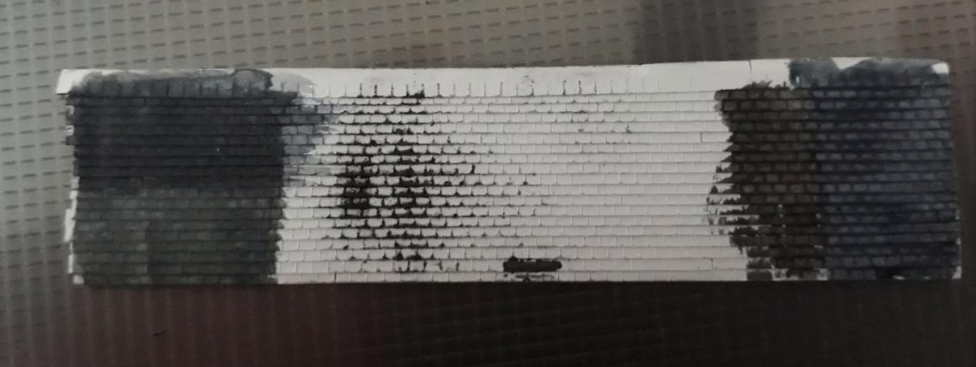
Alisdair showed us his recent experiments in producing roof tiles with the help of a Silhouette cutter. He used 80gsm white self adhesive labels. Plain water colour (on the right) was not very effective. Much better was enamel (on the left, one patch thick, one thin) with thin watercolour on top.
Alisdair's building material of choice is styrene sheet. A recent model of a Highland Railway store was made from Evergreen siding.
His technique for guttering is to use an all-round horizontal frame of styrene, with the gutter simply scribed into the surface. The frame is then cut down to the edge of the gutter and the inner part is cut out before being fixed to the top of the walls.
Alisdair took us through his multi-layer technique to build up windows. The various views in the sketch should help: the numbers identify the same part in each view.


An example of the finished result:
An earlier technique he used to represent window sashes was simply to glue microstrip behind the window apertures:

Mick's building technique starts with hand-cut card parts and brickpaper covering (Builderplus or Howard Scenics), as instanced by these shots of a pigsty for his Callaton layout. The paper is left with overlaps: when joining two pieces at a corner, one is trimmed off first, the part is joined, the overlap form the second one brought round the corner and carefully trimmed, with the white edge removed using a touch of watercolour. A razor blade and a scalpel are indispensable.

A corrugated-iron roof is added from wine-bottle metal foil imprinted with corrugations using two coffee-jar lids:

The sleeper fence is made by cutting individual sleepers from card and gluing them to horizontals of 1/32" or 1/64" plywood.

Finally the bottom of the fence is trimmed flush using a razor blade and a hammer while holding the camera in your teeth. What could possibly go wrong?
Once the blood is cleaned off the fence, it can be planted in the ground and looks very effective. The standpipe added near the corner has flooded the ground - the water is represented using the Gordon Gravett technique of microscope slide cover glass.


That ended the "Buildings" theme, but it was interesting to see how four modellers use very different techniques to achieve such high quality results.

Simon showed us the baseboard legs he has made for Glenfinnan, using IKEA bed slats as raw material. These are nicely seasoned and can quite often be acquired for nothing from discarded furniture. A base plank of 3"x1" is rebated to take the IKEA bed slats. Two slats are used for each leg, with a slot routed in one to take a sliding peg and tightening bolt on the other, so height adjustment is possible. A triangular flap, hinged so it can fold flat for storage, provides stability


We spent some time discussing (yet again!) the possibilities for a new group layout once lockdown has eased. A shed scene may offer possibilities. Our homework is to come up with some concrete ideas.

The next meeting, still likely to be virtual since Scotland will still be in phase 2 of the lockdown relaxation, will be on 11 July.