The Forth and Clyde area group of the 2mm Scale Association meets on the second Saturday of each month, at the Almondell Model Engineering Centre near Livingston in central Scotland. Our members make finescale models to both 2FS standards and ”NFine” 9mm gauge using code 40 track. This blog gives a flavour of what we do. New Association members are welcome, or drop in to a meeting to see for yourself.
Our February virtual meeting was about various aspects of computer aided design. Alisdair, Alasdair, Jim, James, Chris M, Chris G, Simon, Nigel, Stephen, Graham, Andy, Roy, Richard, Mick and Andy took part, setting what is probably a record of 15 at a FCAG meeting. Five members gave illustrated talks.
Jim talked about CAD for etching, which he taught himself in order to produce Caledonian Railway 2mm wagon kits for his own use (also available through his Buchanan Kits venture). He started with TurboCAD and moved to Autocad when the opportunity presented itself mainly for its more convenient user interface. Initially he used CAD to draw paper templates which he stuck to sheet metal, then cut out the parts slightly oversize with a piercing saw, and filed them back to the template edge. As he grew in experience he started to draw designs for chemical etching, with help from Bob Jones amongst others. Some of his learning points:
draw in units and scale later to the chosen size
build up a "library" of drawn parts which can be re-used
enlarge drawn parts to check fit
take full advantage of layers: Jim uses layer 0 as an outline onto which all subsequent layers are aligned.
build thicker parts up from several concertina-folded etch layers, hinged so they align neatly to be sweated together. Where holes are necessary to insert details, make these larger on the inner layers to accommodate slight misalignments
make extra parts for small, easily lost pieces
make sure you thoroughly understand what format your etching firm accepts before sending off a design, and check your software version is not newer than the etcher's version.
Make extensive use of construction lines to align parts, and to place snap points in convenient locations. Master the offset and group-move functions of the CAD tool.
NanoCAD is a free open-source software tool which which seems to have all the functionality
Jim finds necessary for etch design, whether in TurboCAD or Autocad.
Richard gave an alternative view of CAD drawing - he started only two months ago when he wanted to model a relatively large, very rectilinear reinforced-concrete building for his colliery layout. He laid out the basic design grid by making rather enterprising use of Excel:
then used QCAD to draw the etch artwork, which he chose on the basis of RMWeb discussions and learned to use mainly from Adrian Cherry's Youtube tutorials.
He chose PPD in Lochgilphead to etch his design. His learning points included:
make fold lines wide enough. PPD's minimum etch depth is 0.18mm. 0.3mm width works well for a 90 fold in 0.25mm nickel-silver. Long folds can be etched right through for some of their length and, if visible in the finished model, filled with glue or solder. Jim reminded us that fold lines work much better if gently scored with a scrawker or scalpel before folding, especially if they are under-etched.
0.3mm wide tags to join parts to the etch surround would have worked better than the 0.5mm he used
The end result was very satisfying:
Richard's next project is to model the hopper wagons used at Backworth colliery, a 1920 design by Charles Roberts & Co. Richard scanned a scale drawing and imported the jpeg to QCAD so he could trace over it on a separate layer, using construction lines extensively, building up solebars from three layers, and basing axle lengths on the 12.25mm standard in the 2mmSA handbook.
Next we moved on to talk about 3D CAD. Nigel shared some conclusions from his experience with Fusion360 to design loco wheel centres for the 2mmSA. He explained the 3D design process in simple terms:
make a 2D outline drawing
turn it into 3D by linear or rotational extrusion of the outline
remove material by subtractively extruding in the same way
Everything else is pretty much a combination of these three steps.
Fusion360's full-featured version is expensive, but the free cloud version, limited to ten active documents, is perfectly adequate for 2mm model use. Like Autocad, the real benefit of Fusion360 for our purpose is its superior user interface. The 3D versions of TurboCAD or QCAD are functionally just as adequate, but are slower or more awkward to use. Nigel found it easy to work with i.materialise, the Belgian firm which prints the 2mmSA wheel centres. Their automated design analysis tool is very helpful in finding errors before printing, for example tiny areas of inadequate wall thickness which would be hard to spot manually.
Chris G took the discusion to a new level as he described how he combines CAD elements in an end-to-end layout design process. This is no idle boast, since he produces about 30 such designs a year. In every case he starts with an outline of the baseboards to suit the space his client has available. This is drawn in 2D in TurboCAD and the general layout design roughed out on separate layers.
Once the client is happy, the baseboard shape layer is exported as a DXF
file into Templot. If a real prototype is involved, maps are also
imported and shaped to suit the baseboards - Templot has a handy function
to do this.
The trackwork is designed, with points arranged so their tiebars don't fall on baseboard joints or under structural timbers.
The finished Templot design is exported back to TurboCAD and buildings, bridge decks etcetera can be added in full detail knowing that everything will fit as intended.
The baseboard designs are developed in 3D with scenic cutouts where required, and ultimately sent off for laser-cutting.
The client receives a stack of cut plywood parts which fit precisely and
can be assembled into baseboards in half an hour. This type of
integrated design saves enormous amounts of time.
Chris also showed us his CAD techniques for card buildings, using different layers and colours for different card thicknesses.
Alasdair showed us his 3D designs for a Caledonian Railway diagram 46 wagon. His tool is Solidworks, which he uses professionally. Its parametric features allow several outputs to be generated from the same design, for example a set of 2D etch drawings for a chassis in the same design as a body for 3D printing. A couple of hints: enter dimensions for components rather than dragging shapes to points, and don't fall into the trap of adding endless small detail by zooming into components; it will be unprintable or invisible or unbuildable. Or all three!
He also showed us some 3D track design projects based on Easitrac dimensions.
After three hours absorbing all these techniques, our heads were spinning, and there was just time to agree that our next meeting would be on 13 March, with a show-and-tell theme.
Our first virtual meeting in 2021 had the theme of portable toolkits. It was quite instructive to see the alternative approaches of different group members. As before we had a pretty good turnout: both Chrises, Jim and James, Alisdair and Alastair, Mick, Nigel, Richard, Martin, Simon, Tony, Andy, and Graham.
Jim went first. His portable kit travels in a slim wooden box donated by a friend. He added wooden dividers and locators to hold tools in place, and pieces of magnet strip for items like the steel rule.
The box is the permanent location for most of the tools he uses regularly. When manning the 2mmSA demos stand at a show, some other items come with it: a desk lamp, soldering station, a silicone soldering mat, plywood scrap allowing stronger pressure on a workpiece when required, and a brass pad as a surface to cut etch tabs with a curved scalpel blade. The brass pad is also useful as a non-porous surface on which to dispense drops of cyanoacrylate adhesive before applying them where required with a scrap of wire.
Mick uses a lightweight flight-case style box: his example was acquired from Maplin, now defunct, but a large variety are offered via the usual online auction sites. It's about 40x25x15 cm.
Inside, a wooden workboard with rubber feet is placed on top and holds the remaining contents in place.
After lifting the board out, we see a pocket for a folding lamp at the left, a stack of two trays in the middle, and a space for larger tools and a short test track at the right.
We had a short discussion on lamps, since exhibition halls are often so badly lit that a portable lighting source is indispensable. Mick's is by Ottlite, available from eBay, but relatively expensive. It can be separated from its stand for compact storage. Jim’s cheaper battery-powered example came from Squires - not one of their stock lines, but a "show special". There are plenty of alternatives available online.
Mick's stacking trays are made up from mounting board scraps cadged from a helpful picture framer. He uses these to produce made-to-measure stock boxes and storage boxes as well, and has instructed his fellow NEAG group members on his techniques, although you'll have to go back ten years in the archives before you find this mention. By the way, the NEAG blog is well worth an extended read, if only to see the consistently high quality of photos Mick has produced over the years. It doesn't actually explain how these boxes are made though! Mick explained it to us as cutting the parts from card, taping them together with masking tape, then soaking the joints with pva glue and leaving them to dry out.
Here are a couple of the card boxes: for stock storage ...
and for tool storage by theme - in this case, his favoured Electra couplings.
He typically doesn't travel with the whole box however, and prefers to take smaller boxes from within. Here are his boxes for files: cheap ones and decent Vallorbe files sourced from Cooksons Gold.
Another handy source of storage cases for projects is pill boxes. This one provides seven compartments, but other designs (intended for daily use) can be had with four compartments. The lids have to be opened carefully to avoid catapulting small parts into the middle distance.
For illumination, he uses a heavy-duty Makita work lamp, handy for non-modelling projects as well.
Nigel, like Mick, favours flight cases. (Maybe it's an ex-Chairman thing). Scalpels and similar sharp instruments travel in a plastic box with foam liner so the points are out of the way of fingers.
He prefers not to carry heavy or bulky equipment such as soldering kit when visiting friends or demo'ing at shows. Card modelling is much less demanding on transport and on facilities (and the disruption produced) at the destination. A self-healing mat, plus a piece of acrylic for use when a hard cutting surface is required, are in the case.
Another handy tip is to have a brightly-coloured tub for the "project of the day" when moving about the house, or between house and an outside workshop. It forces you to think through planned work before starting.
Chris G. showed us his heavyweight, or at least heavier-weight, solution: a wheeled trolley 80cm high, weighing 12-12kg with contents. His example cost about £40. The advantage is that his tools can live there full-time, and nothing is forgotten when working far from home. It's especially handy at exhibitions where parking is far from the hall.
The sides fold out for easy access.
Below is space for further trays for bulkier items.
Graham also uses a plastic box, but a cheaper design whose sides have a slight draught ... this is not quite as good for storage as the Really Useful or similar boxes with straight sides, and the slope is more likely to dislodge the contents.
There is a lift-out lid tray which allows some items to be easily accessed without unpacking the whole thing:
A seperate box for small tools lives in the main part of the box, as do bulkier items. His folding work light is a USB power bank with a light seemingly added on as an afterthought - but it lasts most of the day at a show. It has lasted five or six years but no longer seems to be available online.
A soldering station, metal iron stand with tip cleaner, cutting mat, soldering mat and sundry magnification aids all travel in the bottom of the box, along with the vital instruction sheets for etches and copies of prototype photos. Forgetting these has a severe effect on modelling productivity!
James suggested the answer to the bulky soldering iron problem - a slim but powerful iron with adjustable temperature, available online for less than a tenner. Another handy tip was Tesco rigid plastic pencil-cases as storage boxes: £1.50 a pop.
Tony's source of storage boxes is Indian take-aways. Tandoori chicken produces an especially useful size.
But his main theme was the benefits of parts checklists. Before starting a build, he assembles lists of the part quantities required, both from the 2mmSA shop and from other sources. Here’s an example:
This saves time during the project and in related projects afterwards. It led to discussion on how this resource could be made more widely available.
Mick revealed that he keeps a work log with each project in its (custom-made) box, logging the hours spent each time the box is opened ... with the "disadvantage" that, several decades later, there is nowhere to hide when the box for an uncompleted project is opened with its tell-tale timesheet ...
Alisdair has a handy metal tool-box with a scrap of cutting mat tucked inside its lid.
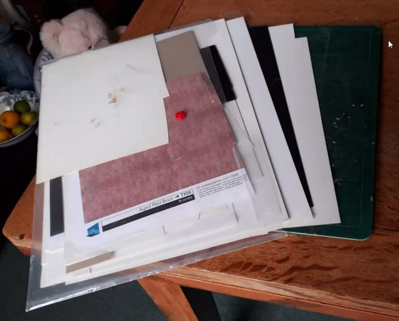
Usually however he carries a larger mat, as well as styrene and brick-papers.
That completed the toolbox review - not the most earth-shattering topic, but it was fun and everyone learned something new.
Attention now turned to the Next Group Layout. Most members have been working on (or at least thinking about) the turnout they have promised to build ... regular readers may recall that we aim to build each of the four turnouts several times, as a learning exercise. Jim has been working on the tandem, and took us through the build sequence he has followed over the last week.
Although Jim usually works with interlaced sleepers reflecting his chosen pre-grouping prototype, we will follow LMS/BR practice for the group layout, so we assume the tandem has been relaid with long timbers
First the timbers were cut to length and secured to the paper Templot template with Pritt. The annotations are for timber length and chairplate type, the latter not followed in every case in the light of experience. The red lines on the template are insulation demarcations. The length of Easitrac base is to show how the next turnout in the unit will match up. If these points were being made for a home layout, it would be much more convenient to make the next turnout as a single unit with the tandem.
With the timbers in place, the first stock rail is added, with a set in the correct place for the switch. Regarding the chairs, designer Laurie Adams' 2mmSA magazine article (Aug/Sep 2018) described adding the chairs after the rail is temporarily held in place by forming the outer jaw, sliding them under the rail edge-first, then raising the inner jaw. Dave Searle devised a bending jig to pre-form both jaws (Feb/Mar 2019 magazine) before sliding them in from the gap between the sleepers. Our tandem builders (Simon and Jim) found these techniques troublesome and preferred to form the chairs with both jaws wide open in the jig (now available as stock item 1-148 from Shop 1), solder them to the sleepers on the template by eye, and only then slide in the rail, push down the jaws and solder in place. This technique also has its disadvantages though, when jaws are accidentally flattened, resulting in a quick bit of surgery to slide the old one out and a new one in. "A bit of a faff" was Jim's conclusion, but he got there nonetheless.
The first crossing vee is built in-situ, from two pieces of rail with the correct taper formed in a jig (Jim uses his own design of taper jig, written up in the 2mmSA magazine for Feb/March 2012). By assembling the crossing this way, the point rail forming the tip of the crossing vee can be placed precisely where the template indicates, then the splice rail can given the correct set-back for smooth running. See the helpful diagrams in section 5.6 of the 2mmSA "Track" book. The tip is gauged from the stock rail with a button-gauge.
Now the second crossing vee is added (to the top left of the shot) in the same way, with the tip gauged from the point rail extending back from the first crossing. Adding the third crossing is more complicated, because its point and splice rails extend back into the knuckle and wing rails of the first two crossings. One is very short and must be formed from a single piece of rail of precisely the correct length between tip and knuckle, if smooth running is to be achieved. This cannot be adjusted later since the rest of the turnout is built assuming this crossing is correctly positioned. An advantage of Jim's filing jig is that it includes an angled plate against which the knuckle bend can be checked until it fits perfectly. The other point-to-wing-rail unit is longer, and required an insulation gap in any case, so Jim used two separate pieces of rail, with a gap around 0.010" judged by eye.
This short piece of rail forms the point rail of the third vee. The tip was tacked in position and the wing rail flange gap at the first vee established using a short length of spare rail as a spacer, with a short straight-edge (the end of a six-inch steel rule held vertically) to ensure the path through the crossing is perfectly straight. Chairs and rail are then tacked, adjusted and finally soldered securely. The splice rail is then added, and the same procedure is followed for the wing rail of the second vee. If these alignments are incorrect, wheelsets will strike the knuckle when trailing through the crossing, risking derailments. The check rail should prevent wheelsets striking the crossing nose in the facing direction, but wobbly wheels or incorrect back-to-back settings will still cause a nose strike if it is not correctly positioned. See figure 2.16 of "Track".
Next, chairs were added for the other stock rail, which was then slid into place:
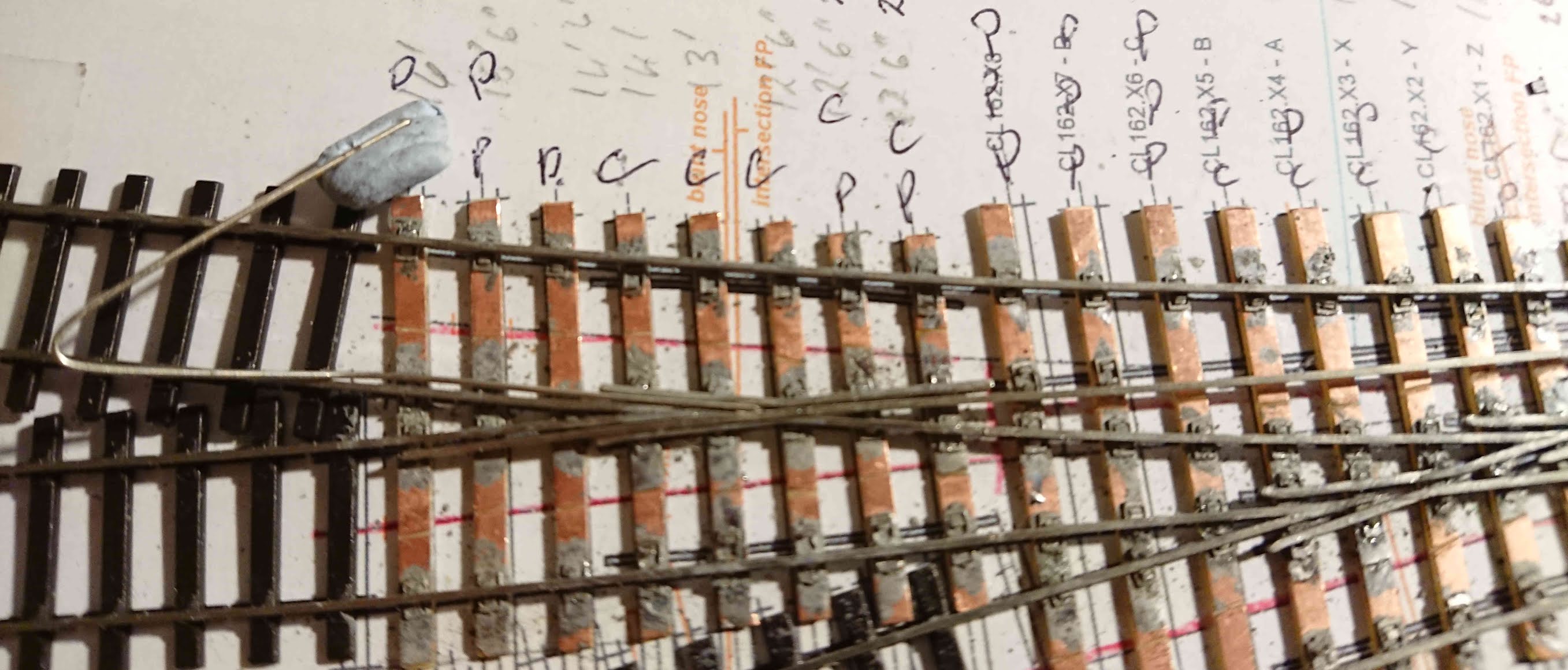
and the knuckles of the other side of each crossing were formed and added. The button gauge and spare rail lengths for the flange gap can be seen in this shot.
In use, the bent piece with the lump of Blu-tac was placed to provide the flange gap for the second wing rail. The straight piece was positioned in the gap of the wing rail already in place, ensuring that the second wing rail's knuckle is aligned correctly. Both pieces were smeared with Vaseline so they were not soldered in place when the chairs were flashed to the rail.
At this stage, wagons were rolled by gravity through the crossings to ensure everything was smooth even without checkrails fitted.
Next, the closure and point rails were progressively added, and temporary tiebars put in place. Rolling tests with wagons under gravity, and pushed by a finger-propelled second wagon, were made at every stage.
Jim derived some satisfaction from finding that wagons rolled through the crossings first time. Skill and experience play their part, but his top tip is to be very particular about accuracy and ensure that every step is correct before moving on to the next. Come to think of it, that is the golden rule often quoted for building locos too.
Having gone through the construction sequence for the tandem, we reviewed Nigel's design for the baseboard, which he had undertaken in Fusion 360. For those of us not professionally engaged with 3D design, it was a revelation to see how animations and live rotation while selecting different drawing elements helps discussion of how exactly the design will work. The intention is to use 3mm ply, laser-cut from the Fusion file, with aluminium angle added to strengthen certain edges.
Some of this discussion had taken place by e-mail, but we went on to consider how to position the proposed S4 Society mechanical lever frame so that linkages to turnouts would work easily and avoid the baseboard cross bracing.
The next virtual meeting will be in 13 February at 2pm, and will focus on CAD tools in 2D and 3D and their use. This should be an interesting session since we have some members who use CAD professionally, others who are experienced amateurs, and others just beginning the journey. I suspect we will run short of time!