
After the customary tea, coffee, chat, soup, bacon rolls, and mince pies (thanks Roy), we proceeded to this month's demonstration. This was by Alisdair, who showed us how to (irreversibly!) modify commercial N gauge metal-tyred wagon wheels for use on 2mm finescale track. His chosen weapon was his 1970s-vintage Unimat lathe, still going strong and useful for all kinds of small modelling jobs.

The 2mm finescale standards are given in the Association Yearbook and online. For convenience the relevant tables are reproduced here.


Alisdair explained he'd first tried modifying wheelsets when he first moved to 2mm scale from 4mm. He found an article in "Model Railways" which recommended using collets to hold wheels. It seemed to make sense, so he turned his own collets in the Unimat from brass and sawed slits so they could be compressed gently in a three-jaw chuck to hold the wheelset by the tyre of one wheel, without removing the wheels from the axle.

The first one didn't work, because he had not tapered the inner diameter to suit the wheel tyre coning. The second one, with taper, worked once then also lost grip. Frustrated, Alisdair put the collets to one side and resigned himself to buying new wheelsets from the 2mmSA shop or sending N wheelsets off to the Association's wheel turning service. Which as we all know is very efficient and remarkably good value. But there was still a nagging wish for the satisfaction of doing the job himself.
A chance conversation with 2mmSA magazine editor (and former FCAG regular) Anthony Yeates suggested a new direction: simply hold the wheelset lightly in the three-jaw chuck , and support the other end at the axle pinpoint in a length of brass tube in the tailstock chuck. The tube acts as a "hollow dead centre", holding the axle concentric and providing enough support for a tool to be used to turn down the wheel flange and face. Here's the tube in position in the tailstock chuck.

To cut the metal, a boring tool was used, since it was small enough to fit between the two wheelsets on the axle. The aim is to do the work without removing the wheels from the axle, which risks destroying their concentricity. After setting and trueing the wheelset in the chuck with the axle in the tailstock support, the first operation is to thin the flange of the wheel in the 3-jaw chuck, then without disturbing the workpiece, thin the tyre of the other wheel. The chuck is then slackened off, the workpiece reversed and trued again, and the second flange and tyre are dealt with.
Here's the operation in detail. First the wheelset is gripped in the three-jaw chuck, which is tightened to hold the wheel lightly.

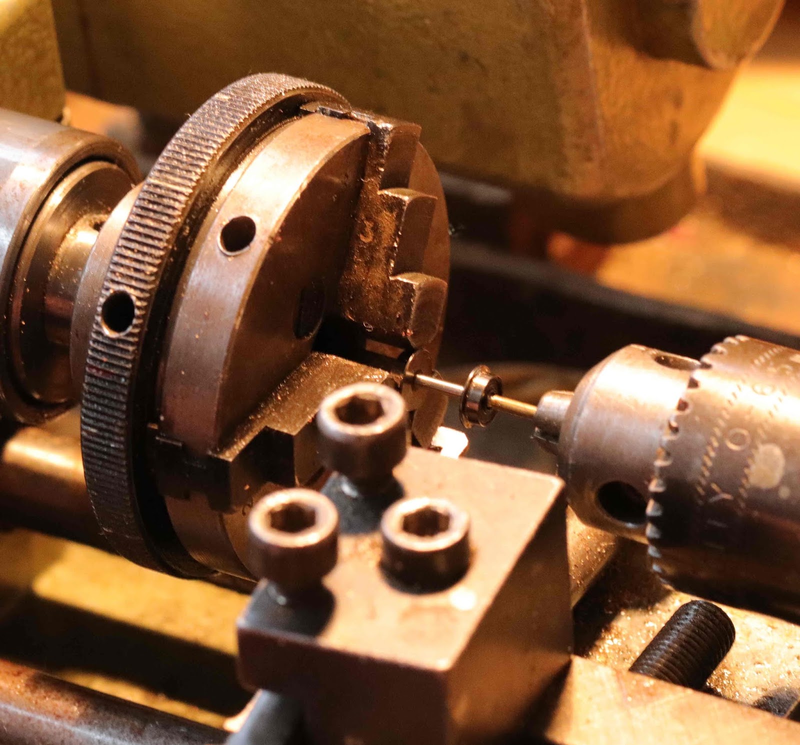
The support tube is placed in the tailstock chuck which is tightened firmly and rotated to check for concentricity. The tailstock is then advanced to the axle end:

and its spindle advanced so the tube is positioned on the axle pinpoint so there is no slack, but without undue pressure.
The chuck is spun once or twice by hand to check the whole thing is concentric, then tightened firmly using its tommy bars. It's important not to overtighten the chuck, or the wheel tyre will be dimpled and ruined. Don't forget to remove the tommy bars from the chuck!


Once the dimension judged by the handwheel gradation is close, the lathe is stopped and the flange dimension checked with the vernier gauge.


Next the tread width of the other wheel on the axle is reduced, with the same technique. Care is required since the wheel may move on the axle if too heavy a cut is taken


The comparison shows the difference in appearance between unmodified and reduced wheelsets.

Alisdair also showed us his latest wheel manufacture efforts, having rejected those he showed us last month.


After this we had intended to do some further work on Sauchenford's fiddle yards. Alisdair was meant to have brought these with him from Glasgow, but unfortunately when he unpacked his car he found he'd left them behind. So there was nothing for it but to unpack individual projects and get on with that.


Note that, where I talk about "a graduated handwheel on the tailstock", and "advancing the tailstock" in the description above, what I should have said was advancing the saddle carrying the tool using the leadscrew. Thanks to Roy Bremner for pointing this out ...
ReplyDelete