A fine sunny day for this month's meeting saw Alistair, Alisdair, Andy, Graham and Jim head well south of the Forth and Clyde valleys to Stephen's house in Lockerbie. The usual wide selection of magazines awaited (does anyone buy as many periodicals as Stephen?) and led to an extended chat session over tea and coffee which merged smoothly into lunch. Square sausage! prompting memories of the late Colin Brady's legendary fry-ups. There were two kinds of cake as well.
This month's Short Talk was by Jim, who had whetted our interest in how he makes Alec Jackson couplings in 2mm scale by showing us some of his tools for the purpose at a meeting he hosted a few months back.
AJs in 2mm scale were first written about, as far as I know, by Bert Groves in the May 1965 2mm SA magazine. Jim also used AJs since way back when, and first wrote up his techniques in the magazine in August and December 1994, with an important update in February 2007; and in MRJ (No 79, 1995, p153). However, he referred us to the standard work, the Scalefour Society's
"Alex Jackson: the Man and the Coupling" (£6 to non-members), which explains their evolution and dimensions for different gauges, as well as their use in 2mm and Jim's development of the coil version.
We were shown the principle of the AJ with a large-scale model:
To couple, the two couplings slide over each other sideways; to uncouple, over a magnet beneath the track, the two couplings slide downwards and are forced sideways by the angled tail, until they pass beyond the opposing tail, before springing back on its other side when the train passes beyond the magnet.
Steel wire, however, does not work in 2mm scale: the magnetic field passes through both couplings and draws both down, so that they stay in the same relationship to each other and do not uncouple. Jim therefore started making his couplings - pre-coil - from 0.006" (0.152mm, 38swg) hard-grade phosphor bronze wire, softened slightly by quickly flicking it through a match flame - not enough to heat it to red heat, which makes it completely soft, in which state it is useless. Without this slight annealing, there is a tendency for the wire to fracture when it is doubled back to form the hook.
An early "conventional" AJ'd wagon using 6 thou PB wire was produced for inspection. In general, Jim works to half the 4mm dimensions, rounded up to the nearest quarter-millimetre.
The couplings have a 1mm step introduced just in front of the headstock, so that the nose is 5mm above rail level.
This allows the couping shaft to rest gently on the underside of the headstock:
Setting the coupling at 5mm above rail level like this ensures the hook passes below the beam at buffer stops, rather than bounding off it.
Coming back to the coil version of the coupling: the idea was to produce a highly flexible coupling in minimal space, by coiling up the 60mm length of spring wire which had proved insufficiently springy in the conventional version - there was a tendency not to couple up due to lack of sideways movement. Several experiments were tried to overcome this, including use of thinner wire and hinged couplings, but eventually the coil turned out best: so well, in fact, that the wire thickness could be increased to 0.008" (near enough 36 SWG, 0.193mm) which, handily, is available from
Eileen's Emporium. This also had the major benefit of making the hook more robust. Making the coil is quite fiddly however, as Jim's demo showed.
First a 60mm length of wire is cut off, and any burrs stoned off the end until it feels completely smooth. The wire is cut is straightened by placing the ball of a finger into the curve of the wire, then drawing the full length of the wire through finger and thumb applying gentle pressure from the thumbnail. After a few passes the wire is straight.
The first job is to form the hook at the end of the coupling. This is simplified using a tool made from brass rod, with a 2.7mm-deep hole, able to take a single thickness of wire, drilled at one end to help form the first bend in the hook, and a 1.5mm hole, able to take a doubled thickness of wire, to help form the second.
The wire is placed into the 2.7mm end and a bend introduced; this is gently worked round into a 180° bend:
then the second bend is made and adjusted to 30° with fingers, judged by eyeball: note here that the pliers are only being used to hold the coupling, the angle is simply bent with gentle finger pressure. Be nice to your wire, Jim advised: treat it gently and bend it slowly to avoid fractures.
If necessary the angle can be checked against the drawing:
The doubled-back part of the tail is strengthened by dipping it in solder paint and touching with a soldering iron. This avoids any roughness which might hinder the sliding action in coupling and uncoupling.
A 1mm-deep step is then added at the correct distance. The first 90° bend is made with pliers, ensuring correct orientation with the hook; then a small steel rule which happens to be 1mm thick is used to help form the step.
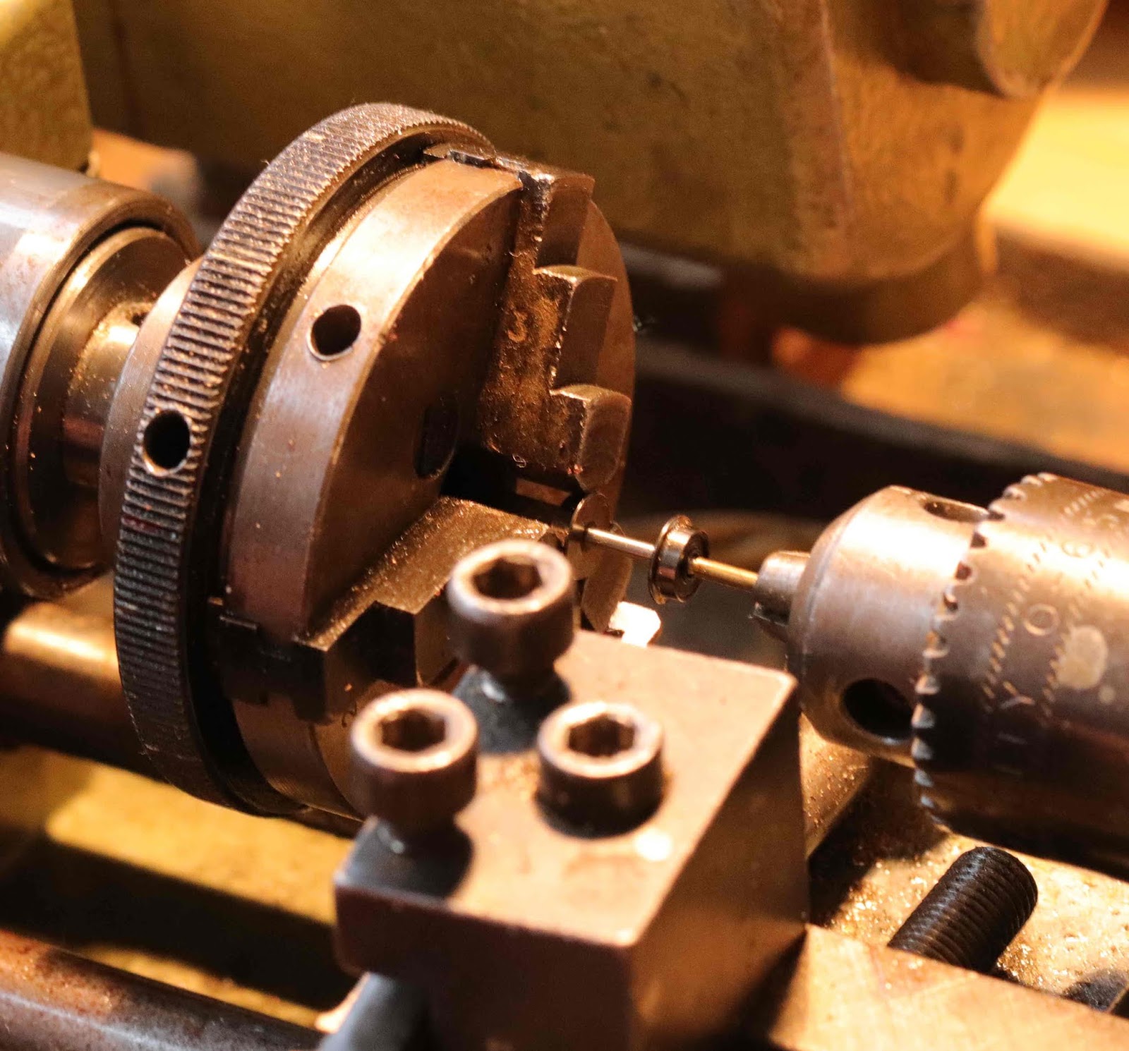
Next, the coil is wound around a length of 1.4mm steel drill rod. The rod has a handle of brass angle attached, with an adjustable clamp and small slots in whcih the hook of the coupling engages to produce a variety of coil-to-hook lengths.
The rod is notched so that the wire can be held tightly, helping form the 90° angle at which the business end of the coupling must leave the coil:
The rod is then held loosely in a pin chuck, so it can rotate; the chuck is clamped in a vice.
The coupling can then be wound using the brass handle to rotate the drill rod, keeping tension on the wire:
Since the wire is a standard 60mm length, a shorter coupling will have a larger coil. The finished coil can now be gently eased off the rod.
To avoid an undesirable bobbing motion when a train is drawn along the track, a lug is placed up the middle of the coil, to prevent it stretching sideways. The lug is formed from an L-shaped length of 0.010" nickel-silver (scrap etch); the short part of the L needs to be about 1.5mm-2mm deep, so that the coil cannot slip over its top:
The lug has to be positioned fairly precisely as far back in the coil as possible, then the tail of the coupling is soldered to the longer side of the L, but without soldering the whole thing solid! This is done in a wooden jig with a slit cut to hold the coupling, with its position adjusted with tweezers. Once positioned, a craft knife is used to hold the wire while an iron is applied, helping avoid solder creeping towards the coil.
Now, with the coupling held horizontally, all the angles are checked and corrected if necessary.
Next, the coupling is mounted on the vehicle using superglue. (Jim uses cheap superglue tubes from pound stores, pricking the tube top then squeezing a little onto a metal plate. the excess is wiped off the tube and Vaseline applied to tube and top; the tubes are then stored upright and are cheap enough to throw away without regret when they harden).
To glue the coupling in place, the wagon is strapped into a little jig, the coupling held in place, and a drop of glue flooded onto the wagon floor, without gluing up the coil.
Next, an iron dropper has to be added so that the coupling can be uncoupled magnetically. Jim uses small iron nails, originally purchased from B&Q in the 1970s for use as buffer heads. Firstly, 4.5mm from the head, a flat is squeezed on the nail shaft using pliers:
Excess flat is broken off, with enough retained to form into a U shape using the steel rule:
A drop of superglue is placed in the U, then the nail is placed on the coupling as close to the wheel axle as possible, set not quite vertical so a little sideways motion is imparted when a magnet attracts the dropper, to aid the uncoupling action. The nail is positioned with tweezers then held in place until the glue goes off.
Jim also showed us how couplings are fitted to vehicles with more underfloor hardware such as brake cylinders:
and on bogies, where the coil is placed below rather than above the coupling: the winding jig's L-clamp is used to adjust the coupling length.
Finally, the fitted coupling nose is adjusted for height and centred using a standard jig: lines drawn on the white plasticard allow the correct setting to be checked:
The nose should be offset towards the hook by a distance equivalent to the diameter of the wire - this causes a slight side pressure which helps prevent inadvertent uncoupling in a train in motion.
One advantage of the coil design is that it makes the coupling very flexible in storage, with less change of damage or distortion which later causes problems in operation. This was demonstrated using a clear plastic box, so we could see how the coupling was simply pushed sideways without damage when pressed against the box wall, but returned to the normal position afterwards.
Jim has completed more than 300 of these couplings. Practice makes perfect!
To bring the story up to date, Jim gave a brief glimpse of the coupling R&D department - however, cameras had to be left at the lab door, so no pictures.
That brought a fascinating demonstration to a close, and allowed a little more work to take place on Sauchenford's fiddle yard.
Alisdair has also been working on scratchbuilt bogie (or pony truck?) wheels for his latest Highland loco. I can't remember if this was to be a 2-4-0 or a 4-4-0, but the wheels are made in his Unimat, with brass centres and steel tyres. The prototype diameter here was 2'6" I think.
Jim showed us his 2mm scale signal wire posts - etched posts with pulley wheels from slices of copper wire - which he has
written up recently on RMWeb.
And so we came to the end of the meeting. Thanks very much Stephen for hosting and for the refreshments. Next month, we plan to meet in Edinburgh.