Sunday 14 March 2021

March 2021 FCAG meeting

Our March meeting attracted 13 participants - Alisdair, Alasdair, Simon, Jim, Stephen, Mick, Nigel, Richard, Chris M, Chris G, Martin, Andy and Graham all zoomed in for a few hours of "show and tell".

Simon went first. He's constructing a turntable fiddle yard for "Glenfinnan", using a router on a trammel to get the radius right.

He's also working on an ex-LNE Coronation stock "beavertail" observation saloon, as modified by BR in the 1950s for use on the West Highland. He started with the basic shell from Simon Dawson's Rue d'Etropal range, available from Shapeways. This shot shows that the print is quite rough, but Simon found it cleaned up very easily, polishing it with sandpaper stuck to bits of wooden clothes pegs (apparently his neighbours are putting motion detectors on their drying greens).

It will need Gresley 8'6" bogies: these were ordered from the shop, received and built all in a week. This shot is of the prototype of course, not the model!

He's also still working on a tandem for the FCAG shed scene layout.

Mick has been implementing advanced DCC settings (with Nigel's help) using jmri decoder pro in order to get his Class 37's lights to behave prototypically - he's added the ability to switch off the red markers at the trailing end when hauling a train, and to light red markers at both ends when stationary on a running line. He showed us this using a mirror so we could see both end of the loco at the same time.

Chris G. has been moving ahead with pointwork for Bosaleck. There are guitar-string droppers (arrowed red) from the point blades which engage in the tubes on the operating units.

He'll shortly start work on an M7 loco conversion.

Nigel has been discussing the group's involvement in sleeper production. The current production line, established by Bill Blackburn, uses a heavyweight guillotine to reduce 2'x3' SRBP PCB sheets into 300mm x 18mm, 19mm or 20mm strips.

Next, the strips are gapped using a circular saw with a table and fence to remove the copper layer but not the SRBP substrate.

Finally a third machine (not illustrated) is used to chop individual sleepers.

These are somewhat inconvenient to store and transport for the proposed group sleeper-production sessions (sleep-overs?). Nigel has drawn up a design for a simpler gapping attachment to fit the vertical slide on a lathe: a jockey wheel keeps the sleeper blank firmly on the table and the saw blade, mounted on an arbor in the lathe, is kept out of harm's way under the table.

Further developments are expected.

Chris M. has been detailing his LMS 4F, inspired in part by Nick Mitchell's excellent tutorial. Boiler backhead fittings under construction, cruelly magnified:


 Reversing crank and coal-dampening c0ck: 

Smokebox detail:

Chimney, dome, water pickup dome and tank filler turned on the lathe:

Jim is continuing to add buildings to Kirkallanmuir along the road leading downhill from the overbridge next the station.

A "kit of parts" was cut out from styrene sheet. The baseplate has holes to locate on dowels on the baseboard: the little blocks of scrap styrene are to strengthen the joint with the wall. Jim runs a fillet of Easitrac glue along the joint as well.

In position:
Detailing:
The next building down the hill is to be based on another local nineteenth-century prototype:

The styrene shell:  

The shell in place:

Richard has been designing etches for pithead gear and for wagons. PPD must be glad he discovered 2mm modelling, he's keeping them busy!

I think I have posted shots of his build of Fencehouses Model Foundry P4 hopper kits before, but he has improved the end stanchions, which are built up from multiple layers of etch, flooded with solder.

They recently made a trip to the paintshop. This shot compares Railtec "NCB" lettering trasnfers on the left, and Fox on the right. His preference is for Railtec, both for price and for ease of application:

He has another twelve of these to build. As if that was not enough, he's also produced an Easitrac point for the FCAG group layout:

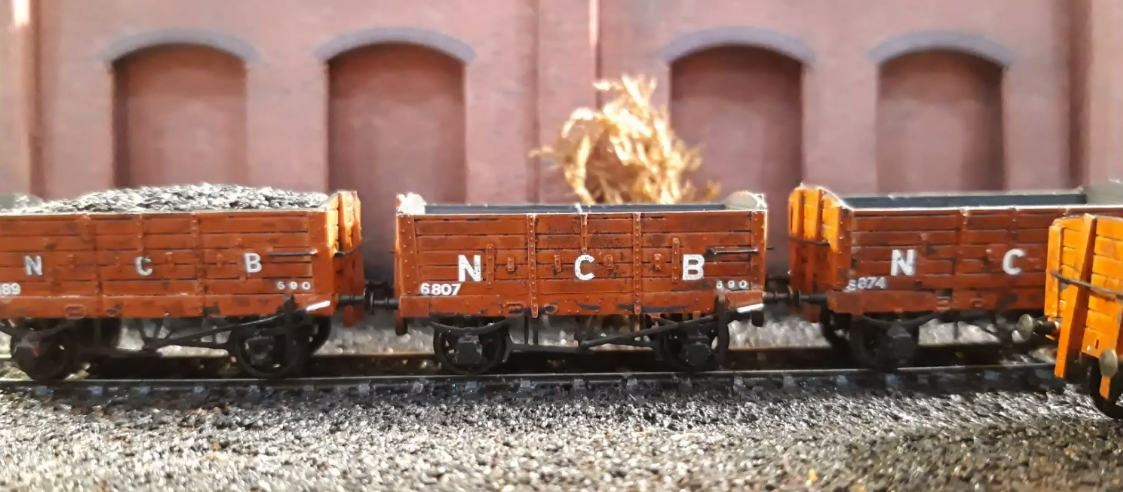
Martin has also been busy with mineral wagons, with several variants of bodies and brake gear:


and with BR Mark 1 DSO and BSO bodies from Masterclass etches via the 2mmSA shop:

Alasdair has been working on turnouts for the group layout as well:

Meanwhile his near-namesake, Alisdair, has advanced his Highland Railway "Yankee Tank" to be ready for painting.


A keepalive capacitor is hidden between the frames

and the tanks, bunker and boiler are filled with lead weight. The superstructure is built on a sheet of thin PCB, which is handy for attaching parts while ensuring electrical isolation. An 0816S 8mm coreless motor from Micromotor powers the loco, with the only reduction being the worm and wheel. The motor runs slightly fast for this to be fully effective with analogue power, but is very controllable using DCC and tweaked CVs.

A hive of activity ... .we will see if it continues as lockdown loosens! 

Our next meeting, still a virtual affair, will be on April 10th: its theme is yet undecided.


Saturday 6 March 2021

February 2021 FCAG meeting

Our February virtual meeting was about various aspects of computer aided design. Alisdair, Alasdair, Jim, James, Chris M, Chris G, Simon, Nigel, Stephen, Graham, Andy, Roy, Richard, Mick and Andy took part, setting what is probably a record of 15 at a FCAG meeting. Five members gave illustrated talks.

Jim talked about CAD for etching, which he taught himself in order to produce Caledonian Railway 2mm wagon kits for his own use (also available through his Buchanan Kits venture). He started with TurboCAD and moved to Autocad when the opportunity presented itself mainly for its more convenient user interface. Initially he used CAD to draw paper templates which he stuck to sheet metal, then cut out the parts slightly oversize with a piercing saw, and filed them back to the template edge. As he grew in experience he started to draw designs for chemical etching, with help from Bob Jones amongst others.  Some of his learning points:

  • draw in units and scale later to the chosen size
  • build up a "library" of drawn parts which can be re-used
  • enlarge drawn parts to check fit

  • take full advantage of layers: Jim uses layer 0 as an outline onto which all subsequent layers are aligned.

  • build thicker parts up from several concertina-folded etch layers, hinged so they align neatly to be sweated together. Where holes are necessary to insert details, make these larger on the inner layers to accommodate slight misalignments
  • make extra parts for small, easily lost pieces
  • make sure you thoroughly understand what format your etching firm accepts before sending off a design, and check your software version is not newer than the etcher's version.
  • Make extensive use of construction lines to align parts, and to place snap points in convenient locations. Master the offset and group-move functions of the CAD tool.

NanoCAD is a free open-source software tool which which seems to have all the functionality Jim finds necessary for etch design, whether in TurboCAD or Autocad.

Richard gave an alternative view of CAD drawing - he started only two months ago when he wanted to model a relatively large, very rectilinear reinforced-concrete building for his colliery layout. He laid out the basic design grid by making rather enterprising use of Excel:

then used QCAD to draw the etch artwork, which he chose on the basis of RMWeb discussions and learned to use mainly from Adrian Cherry's Youtube tutorials. 


He chose PPD in Lochgilphead to etch his design. His learning points included:

  • make fold lines wide enough. PPD's minimum etch depth is 0.18mm. 0.3mm width works well for a 90 fold in 0.25mm nickel-silver. Long folds can be etched right through for some of their length and, if visible in the finished model, filled with glue or solder. Jim reminded us that fold lines work much better if gently scored with a scrawker or scalpel before folding, especially if they are under-etched.
  • 0.3mm wide tags to join parts to the etch surround would have worked better than the 0.5mm he used

The end result was very satisfying:

Richard's next project is to model the hopper wagons used at Backworth colliery, a 1920 design by Charles Roberts & Co. Richard scanned a scale drawing and imported the jpeg to QCAD so he could trace over it on a separate layer, using construction lines extensively, building up solebars from three layers, and basing axle lengths on the 12.25mm standard in the 2mmSA handbook.

Next we moved on to talk about 3D CAD. Nigel shared some conclusions from his experience with Fusion360 to design loco wheel centres for the 2mmSA. He explained the 3D design process in simple terms:

  • make a 2D outline drawing
  • turn it into 3D by linear or rotational extrusion of the outline
  • remove material by subtractively extruding in the same way

Everything else is pretty much a combination of these three steps.

Fusion360's full-featured version is expensive, but the free cloud version, limited to ten active documents, is perfectly adequate for 2mm model use. Like Autocad, the real benefit of Fusion360 for our purpose is its superior user interface. The 3D versions of TurboCAD or QCAD are functionally just as adequate, but are slower or more awkward to use. Nigel found it easy to work with i.materialise, the Belgian firm which prints the 2mmSA wheel centres. Their automated design analysis tool is very helpful in finding errors before printing, for example tiny areas of inadequate wall thickness which would be hard to spot manually.

Chris G took the discusion to a new level as he described how he combines CAD elements in an end-to-end layout design process. This is no idle boast, since he produces about 30 such designs a year. In every case he starts with an outline of the baseboards to suit the space his client has available. This is drawn in 2D in TurboCAD and the general layout design roughed out on separate layers. 

Once the client is happy, the baseboard shape layer is exported as a DXF file into Templot. If a real prototype is involved, maps are also imported and shaped to suit the baseboards - Templot has a handy function to do this.

The trackwork is designed, with points arranged so their tiebars don't fall on baseboard joints or under structural timbers.


The finished Templot design is exported back to TurboCAD and buildings, bridge decks etcetera can be added in full detail knowing that everything will fit as intended.


The baseboard designs are developed in 3D with scenic cutouts where required, and ultimately sent off for laser-cutting.


The client receives a stack of cut plywood parts which fit precisely and can be assembled into baseboards in half an hour. This type of integrated design saves enormous amounts of time.


Chris also showed us his CAD techniques for card buildings, using different layers and colours for different card thicknesses.


Alasdair showed us his 3D designs for a Caledonian Railway diagram 46 wagon. His tool is Solidworks, which he uses professionally. Its parametric features allow several outputs to be generated from the same design, for example a set of 2D etch drawings for a chassis in the same design as a body for 3D printing. A couple of hints: enter dimensions for components rather than dragging shapes to points, and don't fall into the trap of adding endless small detail by zooming into components; it will be unprintable or invisible or unbuildable. Or all three!

He also showed us some 3D track design projects based on Easitrac dimensions. 


After three hours absorbing all these techniques, our heads were spinning, and there was just time to agree that our next meeting would be on 13 March, with a show-and-tell theme.