Our December meeting was once again a virtual affair, using the Association's Zoom account with the Chairman's kind permission. Since it was a truly dreich winter day, I think most of us were glad of the excuse to stay in.
Alisdair, Martin, Jim, James, Tony, Richard, Mick, Simon, Andy, Graham, Chris G. and Nigel appeared on screen for a down-to-earth Show and Tell session. Martin went first and showed a nicely-weathered rake of wagons, which had benefitted from his painting skills from wargaming figures. Unfortunately, I did not get screenshots of his work (sorry Martin) but maybe he'll give us an entire session on weathering another time.
Martin had also recently tackled an an Easitrack turnout kit, which had gone well until he started to file the planing of the switches. This caused problems. We talked about the various methods of tackling this job, and it turned out to be an issue for many of those who'd tried the kit - more of this later. As usual, each expert had a slightly different way of tackling the job, so the discussion took some time.
Martin raised another good question: which is the best 2mm steam outline kit to cut your teeth on? Mick pointed out that the usual advice, namely to find an 0-6-0 tender prototype, is given because this gives twelve contact points for reliable pick-up and thus maximises the chance of something running smoothly first time.
Richard had also tried an Easitrack point kit, and this time I managed to take a screenshot.
Construction was straightforward and took him a week of evenings, but like Martin, Richard found things went wrong when it came to filing and fitting the switch rails. Mick recommended sliding the stock rails through the chairs for three sleepers past the tiebar, allowing the switch rails to be slipped into place. The stock and switch rails can then be unobtrusively bonded with a small strip of brass. Another of Mick's tips was to replace the solder tag on the crossing with a longer piece of brass strip, long enough to pass through the baseboard. This allows the crossing to be removed easily if it's necessary to adjust or replace the closure rails.
Richard was brave enough to show us a cruel close-up of how, in frustration, he had attempted to get the switch tips to sit in neatly against the stock rails, after being told in a previous meeting that joggles were for Great Western modellers only and that porridge-eating, caber-tossing, loch-swimming, hair-shirted inhabitants of Ardnamurchan were not permitted such simple solutions. The alternative he came up with was to file a recess in the stock rails themselves. This caused some concerned murmuring from the experts who pointed out that although this will work well in the facing direction, it is likely to cause problems when passing through in the trailing direction as wheelsets are likely to bounce off the recess when it ends suddenly and derail.
On seeing the photo, the diagnosis was that the planing length of the switch tips is too short. According to the 2mmSA "Track" book, "A" switches should have 11mm planing and "B" switches, 15mm. Sometimes cruel photos have their uses, for diagnosis would have been difficult without it.
It turned out that not only Richard, but several others were slightly confused by the book, which deals with filing of crossing vees and switches in the same section, bouncing around somewhat between the two. The "file-bend-file" technique of filing a taper on one side of the rail until just reaching the web, then bending the rail so that the filed taper is in a straight line with that side of the rail, and finally filing the taper on the other side of the rail, is intended to be used for switch blades as well as crossing rails. Several people mentioned that when filing the second side, it's only necessary to file away the upper head of bullhead rail, leaving the foot substantially complete so that the switch has a little more strength. The wheel flange only runs along the upper head after all.
The experts also mentioned that, although joggles are not their cup of tea, most of them put a slight "set" in the stock rail - a single kink really, rather than the double-kink of the joggle - but only enough to take the rail a few degrees away from straight. This allows the switch rail to sit in more neatly. Easier to do with soldered track than in the Easitrack kit, however. (And ... tell it not in Gath, whisper it not in the streets of Ascalon ... even the Caley used joggles when they had to - such as in a true three-way point. See here).
Further anent track, Andy showed us his tiebar design, which he wrote up in the magazine a few years ago.
James shows us a small test track and power supply unit he completed recently, as well as a DCC track voltage tester he's currently working on. I missed photos of these too - sorry James! - but again, it would be interesting to have more details in a future meeting.
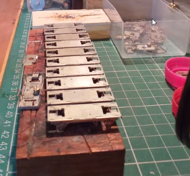
Simon has been batch-building LNER fish wagon chassis. His working practice is based round plastic ice-cream tubs ... it is necessary to spend several evenings eating ice-cream before starting. After that, they are used to keep the different stages of production neatly segregated, so a batch of chassis can be worked on a few operations at a time, slowly (or quickly, in Simon's case) bringing the whole lot to completion.
Other work has included a 2mmSA LNER Toad kit and a mystery-origin kit for a vaguely Southern brakevan picked up out of curiosity at Perth show some years back. No doubt someone knowledgeable (Chris Gough perhaps, our local Southern aficionado!) can tell us what the exact prototype was. Are these things on the end platforms sandboxes?
Finally, Simon showed us the timbers for the tandem he is working on for the group layout. He's a set man, not a joggle man, before you ask.
Tony has also been batch-building, and showed us a box full off Black 5 tender inner frames and cabs. Yes, there are nine cabs in the box, all mostly complete.
Jim showed us the latest progress on Kirkallanmuir's station building, which has gestated from its unfinished state shown here:to a detailed model with window, door and lettering detail added from his own etches. His RMWeb write-up, as usual, gives full details.
The building shell is from 0.040" styrene with 0.020" window sills and 0.010" overlays for quoin details etc. The method of cutting the 40-thou' material is to press heavily an a steel rule and make many light-pressure cuts with a sharp scalpel blade: typically 5 or 6 for 0.020" and more for the thicker material (or score and snap). Jim eschews safety rulers but others spoke highly of them. Alisdair mentioned that cheap Chinese-import rules are in fact better for the job because the poorly-finished edge has the effect of gripping the styrene more firmly that a higher-quailty but smoother-edged rule.
Chris took us though his the latest stages of his LMS 4F build (2mmSA chassis with a Mike Raithby body etch).
Issues he had to solve included the drawbar design, the motor mount, and the gearbox: the chassis etch has a fold-up gearbox but the tabs and slots had not etched well and did not locate properly. Ultimately, and with advice from some more experienced members at a previous physical meeting, it was easier to remove the etched gearbox and fabricate one from brass. The splasher tops in the body kit were another source of issues: Chris learned the hard way that the tops are designed to go above the sides rather than between them - only then is there enough clearance for the wheel flanges.
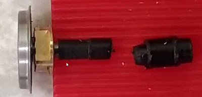
Nigel showed us progress with finescaling the N Gauge Society Hunslet industrial diesel. On taking to bits an early prototype example, he discovered there is very minimal clearance between a spur gear in the model's drive train and a standard (1.5mm) 2mmSA driving axle centred by its drop-in replacement bearing:
His proposed solution is a special axle muff which shaves 0.2mm off part of its length to clear the spur gear. If that does not prove practical after checking for tolerances on more recent production models, a plan B exists using a thinned axle.
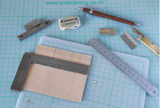
Mick had an intriguing set of illustrations of how to make card wagon bodies from standard file dividers. The prototypes are from local industrial railways. First the sides are drawn on the card:
The model is assembled square:
End stanchions and hopper sides are added:
Here a 2mmSA chassis has been used to complete the model.
The final shot is of a similar North Eastern pre-grouping hopper in card, a model he completed in 1984,
Alisdair brought us up to date with progress on his Highland Railway "Yankee Tank" 4-4-0T. The chassis has advanced to a state where it is square and flat, and everything runs smoothly. The frames are from 0.55mm brass, which he found much more pleasant to use than the thinner material often recommended. They are also blackened with a Carr's proprietary liquid, rather than painted, which will hopefully overcome problems with unsightly chips as the model is handled.
The brake rigging (brass shoes, nickel-silver hangers, PCB cross-shafts, and a wire pull-rod) locateinto a thin tube which receives the pull-rod, visible below.
The boiler was rolled round turned bands, soldered, then cut away for the motor, as seen below.
The tank and cab sides were cut from sheet with a piercing saw.
Boiler fittings have been turned on a lathe with needle files.
That pretty much completed the showing and telling. The next virtual meeting is likely to be on 9 January 2021, with a tentative theme of "travelling toolkits".
Whether you are of the Set or Joggle persuasion, the Forth and Clyde Area Group wishes all 2mm modellers, in Scotland and beyond, a Merry Christmas and a guid New Year tae yin and 'a.


excellent work as always by those north of the border
ReplyDelete